background image

Contents

Introduction

Adaptor replacement

Printer replacement

System A/S

LCD/Touch replacement

Usage

Extension

Installation

Bios

Configuration

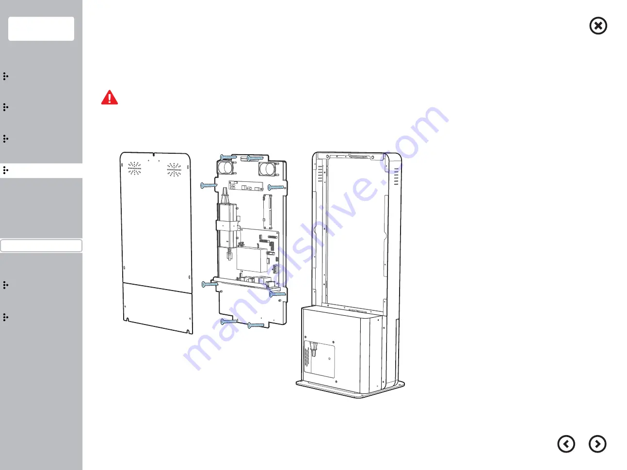
1. Unplug all cables connected with system section.

2. Unscrew 8screws fixing LCD press.

3. Disassemble LCD press.

4. After Repair and replacement, install system parts.

  Touch panel can be detached, please watch out.

- System cover is heavy, when you try to disassemble the device, please watch out not to happen falling accident.

- When you try to unplug the cable, please watch out cable is not damaged from sharp press and other materials.

 LCD/Touch Replacement

Product extension

19

Summary of Contents for M-215D

Page 1: ...M 215D User manual Safety precations Before use the product please read this manual carefully...

Page 2: ...omposition Main Jumper setting 21 22 26 I O Pin map 27 Configuration System composition Contents Introduction Installation Usage Wall mount installation Part name Function Exterior design Product Insi...

Page 3: ...oval and any circuit damage Please use the product in the wide area having ventilation Please avoid direct sun ray humid area hot and frequent temperature change area Do not connect the product with h...

Page 4: ...ication can be changed without any notice as purpose of improving quality M 215D is tested fully to certify it s quality and durability based on Hanasis excellent technology M 215D is applied gorgeous...

Page 5: ...ial RF COM Wall mount Hanasis wall mount Camera USB Camera intel J1900 intel 6th 7th i3 i5 mSATA 64GB Desk 339 W x 265 D x 791 H mm Stand 428 W x 450 D x 1604 H mm CPU SSD 44GB DDR3 Max 8GB 4GB DDR4 M...

Page 6: ...ons Part name Function Installation Usage Extension Bios Configuration Front Rear Stand Exterior design Parts name and Product Function Lock Touch monitor Printer Barcode Power cable Lan cable Rear co...

Page 7: ...n Usage Extension Bios Configuration Exterior design Product Inside Product I O Product Inside Parts name and Product Function Please open the door after unlocking the locker by the key key Rear cable...

Page 8: ...Monitor power jack 8 DIN 3pin 24V DC System power provision jack 9 D SUB 9pin COM 10 D SUB 9pin COM Printer Interface Parts name and Product Function Front Rear Inner LAN AC IN COM2 COM3 LINE OUT COM4...

Page 9: ...figuration 9 Stand is heavy Please watch out not to happen any falling accident Stand installation and Precaution Stand installation stand is optional item Exterior please follow below steps Put the b...

Page 10: ...ation Power connection Power on off Usage Extension Installation Bios Configuration Fix the wall mount base on the wall by using 4 screws When you have Desk type model Please remove the base plate to...

Page 11: ...rew Press the power button inside the door 3 Stand is heavy Please watch out not to happen any falling accident Power connection and Precaution Power connection 11 PWR Switch USB COM6 COM5 USB Power b...

Page 12: ...d well or not While the system is on do not turn off the system on purpose In case of unplugging power cord forcibly data loss and system error can be happened so please do not turn off the system on...

Page 13: ...the printer hook as image indicated Please close the printer cover after pull printer paper with going through the front door Please watch out to happen printing jam on the printer head Printer paper...

Page 14: ...s Configuration Body disassembling Adaptor replacement 14 1 Dissemble system cover by unscrewing 4screws on the rear side Disassemble rear cover by unscrewing 2screws Unscrew rear cover 4screws and 3s...

Page 15: ...cable fixed with mainboard and adaptor power cable 2 Unscrew 2 screws fixing adaptor hold 3 Fix new adaptor After replacing new adaptor please watch out cable is not disturbed from other parts gap Sy...

Page 16: ...tem adaptor 1 Disassemble adaptor power cable fixed with printer and power cable 2 Unscrew 2screws fixing adaptor holder 3 Install new adaptor After replacing new please watch out cable is not disturb...

Page 17: ...nlock the locking device open the door 2 Disassemble power cable and printer cable 3 Detach the printer cable by unscrewing 4 screws After replacing the parts please watch out cable is not disturbed f...

Page 18: ...ation 1 Unplug all cable connected with mainboard 2 Unscrew 4 screws fixing mainboard 3 Replace new mainboard After replacing the parts please watch out cable is not disturbed from other parts gap Sys...

Page 19: ...screws fixing LCD press 3 Disassemble LCD press 4 After Repair and replacement install system parts Touch panel can be detached please watch out System cover is heavy when you try to disassemble the d...

Page 20: ...uld be connected in advance Please refer to our website for better bios set up understanding Bios include basical system setting please watch out system operate improperly by wrong setting index 1 Ple...

Page 21: ...Contents Introduction Usage Extension Installation Bios Configuration System composition 21 System composition Main board composition Main Jumper setting I O Pin map...

Page 22: ...a e H n i P R S M r e d a e H n i P r e k a e p S r e i f i l p m A r o t c e n n o C 4 M O C r o t c e n n o C 5 M O C r o t c e n n o C 6 M O C 6 5 B S U r e d a e H n i P 0 2 B S U r e p m u J e g...

Page 23: ...P 8 USB 3 4 USB3 0 3 COM 2 DSUB9P 9 LAN 2 RJ 45 4 VGA 10 Audio Jack Mic In 5 COM 3 DSUB9P 11 Audio Jack Line Out 6 USB 1 2 USB2 0 3 COM 2 2 COM 1 1 DC IN 24V 5 COM 3 4 VGA 7 LAN 1 6 USB 1 2 9 LAN 2 8...

Page 24: ...18 AT ATX Mode Jumper 4 PCIe Power Connector 19 Front Panel Pin Header LED Button 5 PCIe Slot 20 CMOS Clear Jumper 6 Touch Panel 5 Wire 21 Coin Cell Battery 7 Mini PCIe Slot mSATA 22 SATA Power Connec...

Page 25: ...9P 8 USB 3 4 3 COM 2 DSUB9P 9 LAN 2 RJ 45 4 VGA 10 Audio Jack Mic In 5 COM 3 DSUB9P 11 Audio Jack Line Out 6 USB 1 2 Link LED Activity LED LAN JACK Status Description Status Description Off No Link Of...

Page 26: ...ion 26 Please refer to next image for jumper setting Connection It means jumper cap blocks all pins Open Jumper cap do not block the pin at all 1 2 pin are blocked by jumper cap When you forgot bios p...

Page 27: ...sition Main Jumper setting I O Pin map COM 4 port RJ 45 8 8 8 No Signal Description 1 2 3 4 5 6 7 8 N C DSR TXD RXD RTS CTS GND DTR 8 1 COM 1 2 3 4 Serial port DSUB 9 Pin I O Pin map 27 5 1 9 6 No Sig...

Page 28: ...Main Jumper setting I O Pin map COM 1 2 3 4 LAN DC OUT USB LAN port RJ 45 with LED DC OUT JACK I O Pin map 28 No Signal Description 1 2 3 12V GND GND 1 3 2 No Signal Description 1 2 3 4 5 6 7 8 MD0 MD...

Page 29: ...http www hanasis com 17 Saneop ro 155beon gil Gwonseon gu Suwon si Gyeonggi do 16648 KOREA Direct 82 70 4732 5264 Fax 82 31 297 4381 Email smkim hanasis com...

Reviews: