HAMWORTHY HEATING LTD
16
PUREWELL VariHeat he
500001155/F
6) On Failure to sense presence of a flame the boiler will go to
lock-out.
7) Turn off the gas & electrical supplies to the boiler.
8) Carefully reconnect the electrical plug to the gas valve and
secure with the appropriate screws.
9) Turn on the gas and electrical supplies to the boiler and press
the reset (Enter) button to remove the ‘lockout’ condition.
The boiler will commence the ignition sequence. This time when
the gas valve is energised, the gas will light.
•
At the end of the 5 second ignition proving period, the hot
surface igniter will be switched off and the fascia display will
change to “ BLR:RUN” .
•
After a period of 15 seconds the fan will alter speed and the
burner modulation will be set according to the heat load.
•
If after the 5 second flame proving period the flame signal is
below 1µA the boiler will shut down and attempt one restart.
As the boiler approaches the set point temperature, the % rate will
reduce on the display from 100%
7.3.2 Safety Checks
7.3.2.1 To check for correct operation of the controller, with the boiler running, carefully disconnect the flame
probe lead from the flame probe.
The boiler will shutdown, attempt to relight once & then lock out causing
’no flame ign’
to appear on the display.
Carefully reconnect the probe lead then press the reset (Enter) button to recommence the light-up sequence.
7.3.2.2 With the boiler firing, turn off the gas isolating valve and the boiler will shut down in ‘Blocked’ ‘ mode
showing
‘BLR:Low Gas Pres’
on the display. Wait at least 30 Seconds before opening the gas Isolating valve
when the block will clear and the boiler will recommence the light-up sequence.
7.3.3 Flame Signal Assessment
The flame ionisation signal generated whilst the boiler is firing, can be viewed directly from the display screen.
The value is set to read dc
µ
A. Refer to
8.7.1.3.
7.3.4 - Adjusting the settings of the boiler
The desired Flow temperature setpoint can be set as follows:
With the boiler showing one of the Status Screens
,
by pressing the Up / Down key a further screen is presented
showing the actual setpoint (factory set to a maximum flow temperature of 85°C). Further pressing of the Down /
UP keys will increase or decrease the setpoint in 0.5°C increments within the limits set in the program.
After changing the setpoint to the desired value the ‘Enter’ key must be pressed to store the value.
Note:
the screen will revert back to the normal Status Screen after a few seconds.
Should a set point higher than 85°C be required, please contact Hamworthy Heating, as programming for
a higher maximum outlet temperature is restricted by a factory set access code.
7.3.1 Lighting the boiler
1) Ensure that both gas and electrical supplies are isolated from the boiler.
2) Disconnect the electrical plug to the gas valve by loosening the securing screw(s) and pulling off.
3) Turn on the gas (see Figure 7.2.1) and electrical supplies to the boiler. A gas supply pressure above 12.5 mbar
will remove the Low Gas Pres block and the fascia display will read BLR:OFF
PMP:OFF
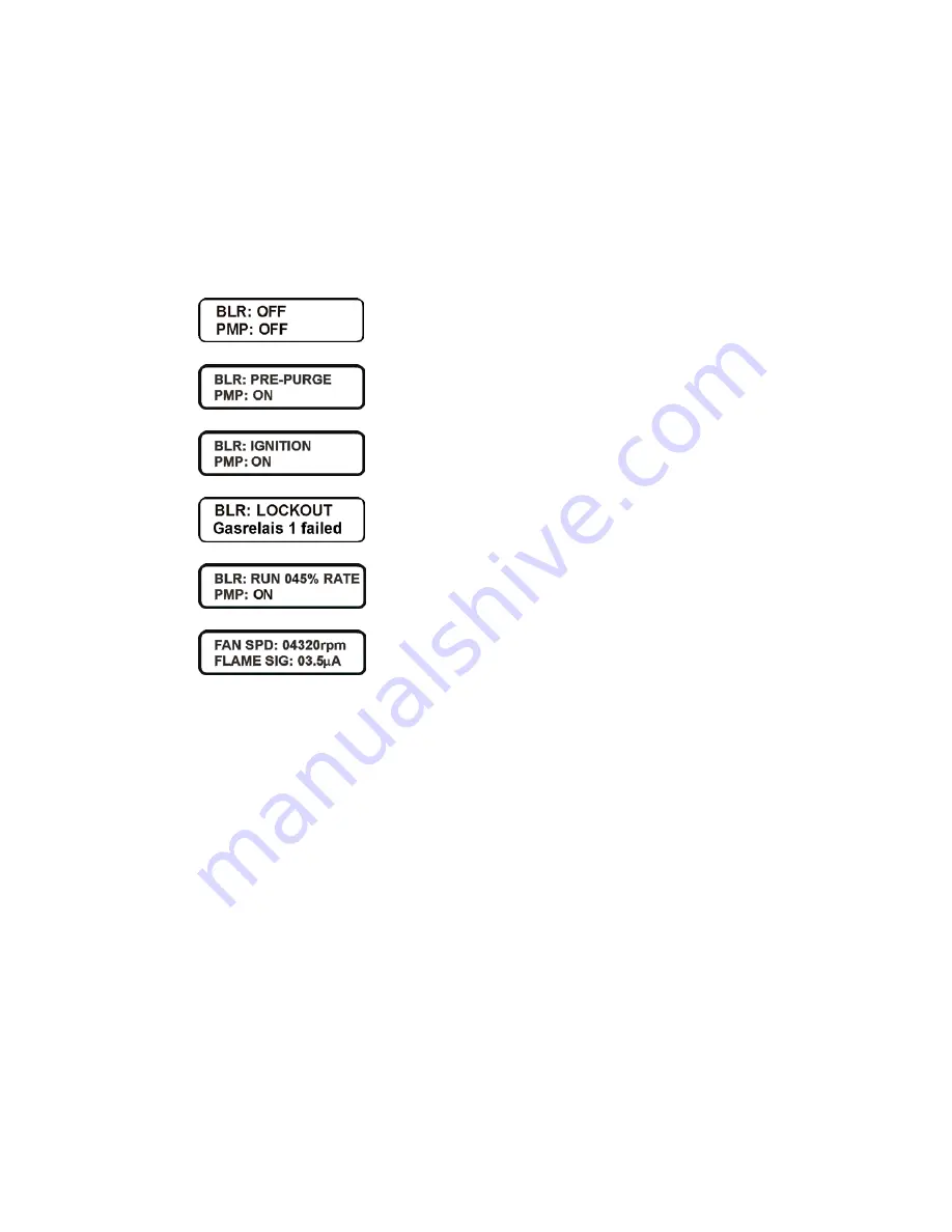
4) To initiate the start-up sequence, press the On/Off (Enter) button. The boiler will run through it’s start-up
sequence and the display will change as per figure 7.3.2 providing that the remote on/off contact is made and/or
the BMS system is in demand.
5) Check that the Hot surface Ignitor begins to glow, by looking inside the boiler through the oval viewing window
within the recess at the top right hand side of the boiler. (At this point, no gas is present in the boiler so no ignition
occurs).
Figure 7.3.2 - Start Up Display Sequence


