


©1998 Hamtronics, Inc.; Hilton NY; USA. All rights reserved. Hamtronics is a registered trademark. Revised: 4/2/03
- Page 7 -
trimmer cap C6 can also short to the
ground plane and require such spac-
ing away from the board.
Table 4. Typical Test Point Voltages
TP1 Tuning V. Normally set at +4Vdc
TP2 Buffer
approx.
+5Vdc
TP3 Sig. Level With SQUELCH control
fully ccw, varies from -0.5
Vdc with no to +0.85 Vdc
full quieting.
TP4 Freq.
Varies with frequency of
input signal. Voltage at
this point normally is ad-
justed for +3.3Vdc with a
signal exactly on fre-
quency. Can vary a little
without being a problem.
Table 5. Typical Xstr DC Voltages
Xstr Stage
E(S) B(
G1) C(D) G2
Q1 vco
1.0
1.5
7
-
Q2 doubler
0
0.65
5.2 -
Q3 buffer
0 0.65 4.6 -
Q4 dc filter
7.0
7.6
7.8 -
Q6
RF ampl
0
0
8
4
Q7 Mixer
0.5 0
8 2.6
Q8 5V
regulator 5 5.6 8 -
Q9 sq.
open
0 0
8 -
sq.
closed 0 0.65
0.1
-
Table 6. Typical IC DC Voltages
U1-1 4
U1-2
4
U2-1 2.1
U2-10 2.5
U2-2 5V
locked
U2-11 2.5
(2.5V unlocked) U2-12
5
U2-3 8
*
U2-13 3
*
U2-4 8
*
U2-14 5
U2-5 8
U2-15 *
U2-6 0-8 (4V tuned)
U2-16
*
U2-7 0
U2-17 5
U2-8 4.8
U2-18 0
U2-9 5
*
U2-19 0
* = pin not used
U2-20
2.3
U4-1: 8
U4-10: 0.75
U4-2: 7.5
U4-11: 1.4
U4-3: 7.6
U4-12: 0.55 (with
U4-4: 8
sq. just closed)
U4-5: 7.6
U4-13:
U4-6: 7.6
0V (sq. open),
U4-7: 7.6
7.6V (sq. closed)
U4-8: 8
U4-14: 0
U4-9: 3.3 (Varies
U4-15: 0
w/ freq.)
U4-16: 1.8
U5-1: 0
U5-5:
0
U5-2: 0
U5-6:
6
U5-3: 0
U5-7: 13.6
U5-4: 0
U5-8:
7
Table 7. Typical Audio Voltages
Audio Test Point
Normal Level
U4-9 (Discriminator)
3V p-p audio
E4 (Disc Output)
2V p-p audio
TP-6 1V
p-p
audio
E1 (Repeater Output)
1V p-p audio
U4-11, top of R27
2.5V p-p noise
(noise ampl output)
Top of Vol Cont R32
300mV p-p audio
U5-2 (af ampl input)
0 to 100mV p-p
(depends on
volume control)
U5-6 or E2
0 to 8V p-p audio
(speaker ampl output)
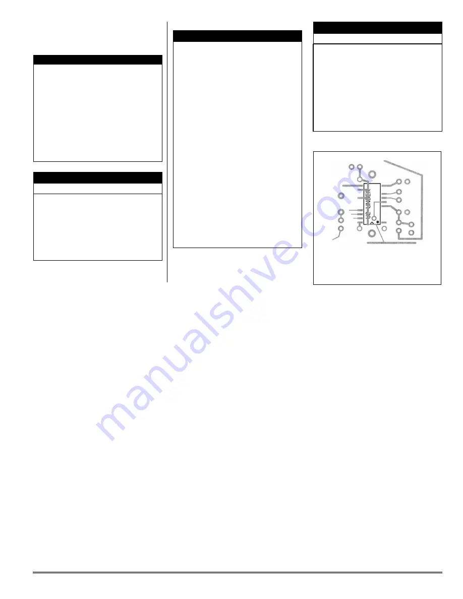
Figure 1. Placement of U2
Under PC Board (dot is pin 1).