HAMPTON BAY HOLLY SPRINGS 57281 Use And Care Manual Download Page 6

6

Installation

MOUNTING OPTIONS

WARNING:

 To reduce the risk of fire, electric shock or 

personal injury, mount to outlet box marked “Acceptable 

for fan support of 35 lbs. (15.9 kg) or less”, and use 

screws provided with the outlet box. An outlet box 

commonly used for the support of lighting fixtures may 

not be acceptable for fan support and may need to be 

replaced. If in doubt, consult a qualified electrician.

If your ceiling fan does not have an existing UL-listed mounting 

box, then install one using the following instructions:


Disconnect the power by removing the fuses or turning off 

the circuit breakers.


Secure the outlet box directly to the building structure. Use 

the appropriate fasteners and materials. The outlet box and 

support structure must be securely mounted and capable of 

reliably supporting 35 lbs. (15.9 kg). Use only UL Listed outlet 

boxes marked “Acceptable for Fan Support of 35 lbs. (15.9 kg) 

or less.” Do not use a plastic outlet box.

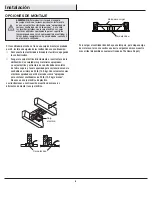
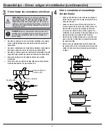
The illustrations below show two different ways to mount the 

outlet box.

To hang your fan where there is an existing fixture but no ceiling joist, 
you may need an installation hanger bar as shown above
(available at any Home Depot store).

Outlet Box

Outlet Box

Outlet Box

Hanger Bar

Summary of Contents for HOLLY SPRINGS 57281

Page 1: ...5 HD HAMPTON HAMPTONBAY COM THANK YOU We appreciate the trust and confidence you have placed in Hampton Bay through the purchase of this ceiling fan We strive to continually create quality products de...

Page 2: ...void possible electrical shock turn the electricity off at the main fuse box before wiring If you feel you do not have enough electrical wiring knowledge or experience contact a licensed electrician W...

Page 3: ...r the warranty invalid There is no other express warranty Hampton Bay hereby disclaims any and all warranties including but not limited to those of merchantability and fitness for a particular purpose...

Page 4: ...4 Part Description Quantity AA Pull chain 2 BB Plastic wire connector 3 HARDWARE INCLUDED NOTE Hardware not shown to actual size Pre Installation continued AA BB...

Page 5: ...it fitter assembly 1 F Glass shade 1 Part Description Quantity G Blade 5 H Blade bracket flange screws pre installed 5 I LED bulbs 9 5 Watt maximum 3 IMPORTANT This product and or components are gover...

Page 6: ...instructions Disconnect the power by removing the fuses or turning off the circuit breakers Secure the outlet box directly to the building structure Use the appropriate fasteners and materials The out...

Page 7: ...t on the top of the fan motor assembly B with the hook on the mounting plate A so that it is securely suspended Then connect the wiring to your fan according to step 3 Making the Electrical Connection...

Page 8: ...es to the household green or bare wire using a wire connecting nut BB Connect the fan motor white wire to the household white wire using a wire connecting nut BB Connect the fan motor black and blue w...

Page 9: ...ee screws removed at the beginning of this step to secure the light kit fitter assembly E Mount the fan blades G to the blade bracket H by aligning the three key slot holes in the blade G with the thr...

Page 10: ...1 DD EE QQ E EE NN B F E I AA The glass holder Finial Assembly Assembling the Fan without the Light Kit Remove the three light kit mounting screws QQ on the black bracket below the fan motor assembly...

Page 11: ...height and number of fans The slide switch XX controls the direction of the blades forward switch left or reverse switch right Warm weather Forward A downward airflow creates a cooling ef fect This al...

Page 12: ...on the ceiling Rotate the fan until the next blade is positioned for measurement and measure from the same point on each blade to the ceiling Repeat for each blade Any measurement deviation should be...

Page 13: ...problems missing parts Before returning to the store call Hampton Bay Customer Service 8 a m 7 p m EST Monday Friday 9 a m 6 p m EST Saturday 1 855 HD HAMPTON HAMPTONBAY COM Retain this manual for fu...

Page 14: ...p m Este 1 855 HD HAMPTON HAMPTONBAY COM GRACIAS POR TU COMPRA Apreciamos la confianza que has depositado en Hampton Bay al comprar este ventilador de techo Nos esforzamos para crear constantemente p...

Page 15: ...ositivo de control de velocidad de estado s lido ADVERTENCIA Para evitar una posible descarga el ctrica corta la energ a el ctrica en la caja principal de fusibles antes de instalar el cableado Si cre...

Page 16: ...validar la garant a No hay ninguna otra garant a expresa Por este medio Hampton Bay queda exonerado de todas y cada una de las garant as incluyendo pero sin limitarse a aquellas de comercializaci n e...

Page 17: ...4 Pieza Descripci n Cantidad AA Interruptor de cadena 2 BB Conector pl stico para cables 3 HERRAJES INCLUIDOS NOTA No se muestra el tama o real de los herrajes Preinstalaci n continuaci n AA BB...

Page 18: ...it de luces 1 F Pantalla de vidrio 1 Pieza Descripci n Cantidad G Aspa 5 H Soporte del aspa brida tornillos preinstalados 5 I Bombillas LED 9 5 W como m ximo 3 IMPORTANTE Este producto o sus component...

Page 19: ...ad retirando los fusibles o apagando los cortacircuitos Asegura la caja el ctrica directamente a la estructura de la edificaci n Usa sujetadores y materiales apropiados La caja el ctrica y estructura...

Page 20: ...del motor del ventilador B con el gancho de la placa de montaje A para que quede suspendido de forma segura Luego conecta el cableado a tu ventilador seg n lo indica el paso 3 C mo hacer las conexione...

Page 21: ...es verde o pelado del hogar usando una tuerca de conexi n de cables BB Conecta el cable blanco del motor del ventilador al cable blanco del hogar usando una tuerca de conexi n de cables BB Conecta los...

Page 22: ...talar los tres tornillos quitados al inicio de este paso para asegurar el conjunto del soporte del kit de luces E Monta las aspas del ventilador G al soporte de aspa H alineando los tres orificios tip...

Page 23: ...r el ventilador sin el kit de luces 1 DD EE QQ E EE NN B Ensamblaje C mo instalar el conjunto del soporte del kit de luces Quita los tres tornillos de montaje del kit de luces QQ del soporte negro deb...

Page 24: ...techo y la cantidad de ventiladores El interruptor deslizante XX controla el sentido de giro de las aspas adelante hacia la izquierda o en reversa hacia la derecha Clima c lido Hacia adelante Un flujo...

Page 25: ...nta de una de las aspas Mide desde un punto en el centro de cada aspa a un punto en el techo Rota el ventilador hasta que la siguiente aspa est en posici n para medir y mide desde el mismo punto en ca...

Page 26: ...es Antes de regresar a la tienda llama al servicio al cliente de Hampton Bay De lunes a viernes entre 8 00 a m y 7 00 p m Este y los s bados de 9 00 a m a 6 00 p m Este 1 855 HD HAMPTON HAMPTONBAY COM...

Reviews: