


13
PREPARING THE TRANSMITTER
Operation
NOTE:
Batteries will weaken with age and should be replaced
before leaking takes place as this will damage the remote
control. Dispose of used batteries properly and keep them out
of the reach of children.
LEARNING PROCESS
NOTE:
The dip switch in the battery compartment has been set
on “0” position and paired for your convenience. If you have two
or more fans, please follow steps below to control each fan
independently.
NOTE:
If installing multiple fans on separate remotes, only
the fan being programmed should have AC power turned ON.
All other fans, even if they have already been programmed,
should have AC power OFF so they do not memorize other
remotes during the learning process. Separate the fan power
switches by approximately 2 meters.
CC
L
APRENDER
LEARN
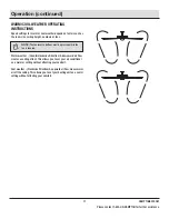
Remove the battery cover by pressing firmly on the arrow and
sliding the cover off.
Install two 1.5V AAA batteries (CC) (included).
Replace the battery cover on the remote control (L).
Ensure AC power to the fan is OFF to begin the learning process.
Slide the dip switch in the battery compartment to the "1" position.
Turn the fan’s AC power ON.
Within 60 seconds of turning AC power on, press and release the
"LEARN" button located in the remote's battery compartment to
enter the learning function. Once the fan has detected the remote
controls's frequency, the down light of your fan, if applicable, will
blink, and the fan blades will start to spin.
The fan will now accept commands from the added remote.
The learning process causes any installed fan within range to
memorize a remote control. Fans can learn five remotes.
To add a remote to your fan’s memory, use the steps below:
L
APRENDER
LEARN
LEARN
HAMPTONBAY.COM
Please contact 1-855-HD-HAMPTON for further assistance.


