10
Assembly (continued)
7
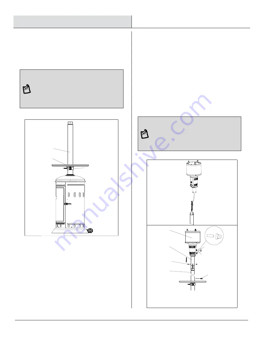
Assembling the Table
8
Assembling the Burner
Assembly
□ Attach the Table Assembly (G and H) to the Post
(D).
NOTE:
When the Table (G) is well attached,
please follow the steps below to adjust the
height:
a. Adjust the grip until it is vertical to the Post.
b. Adjust the height of the table as you like.
c. Fix the position of the table by turning the grip
clockwise.
d. Turn until the grip is fixed.
□ Feed the valve and gas hose and connect the
Burner Assembly (C) to the Post (D).
□ Feed the valve and gas hose into and go through
the Post (D).
□ Screw the Burner Assembly (C) onto the Post (D)
until the holes on the Upper Post Assembly (N) are
aligned to holes on top of the Post (D). Attach using
three M5 x 10 mm Pan Head Bolts (DD). Ensure
they are fully tightened.
□ Reassemble the M5 x 10 mm Bolt (1) to the Post
(D) in order to limit the height of the Table (G).
NOTE:
a. Open the igniter cap by unscrewing the cap
counterclockwise.
b. Take out the battery included in the pack of
Instruction manual.
c. Insert the battery to the igniter.
d. Screw the igniter cap back
D
G
H
M5 X 10 Pan Head Bolt
X 3
DD
D
DD
N
C
+
-
Ignltor
Battery
M5 X 10 mm Bolt
1
Ignitor


