background image

             Multi Effect 1

400

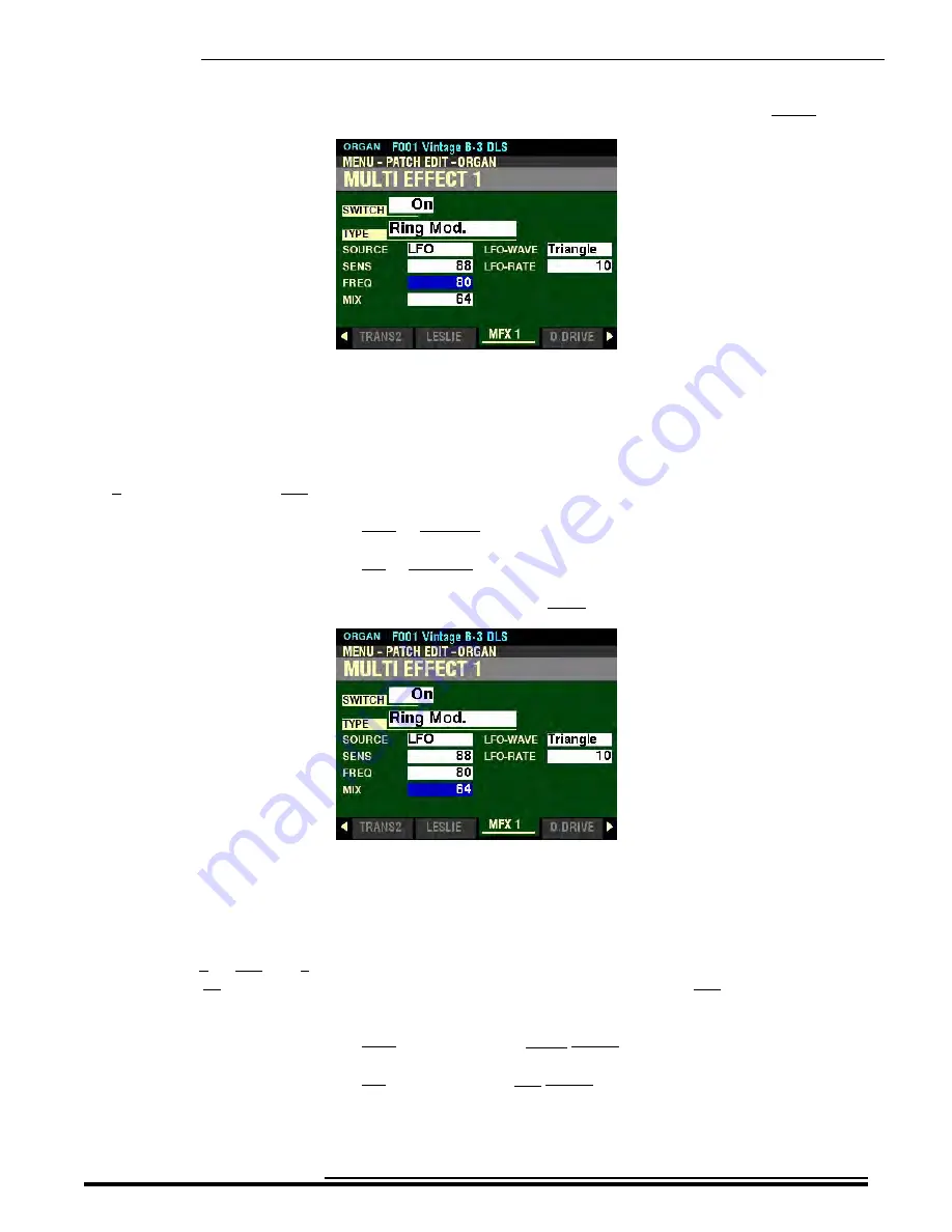
From the screen shown on the previous page

, press the DIRECTION “

q

” button once.

The box to the right of “FREQ” should be highlighted.

RES - Ring Modulator Frequency

This Parameter allows you to adjust the central frequency of the Ring Modulator effect.  You can select from
0 (lowest frequency) to 127 (highest frequency).

Turn the VALUE knob to the right to increase the frequency.

Turn the VALUE knob to the left to decrease the frequency.

From the above screen, press the DIRECTION “

q

” button once.

The box to the right of “MIX” should be highlighted.

FREQ - Ring Modulator Mix

This Parameter allows you to adjust the volume balance between the “dry” and the effect sounds.  You can
select  from  0  to  127.    At  0  only  the  “dry”  sound  is  heard.  The  effect  level  becomes  greater  as  the  value
increases. At 64 the ratio between the “dry” and the effect sounds becomes 1:1. At 127” only the effect sound
is heard.

Turn the VALUE knob to the right to emphasize the Effect Sound.

Turn the VALUE knob to the left to emphasize the Dry Sound.

Turn the VALUE knob to make your selection.

HA<O> 

SK  PRO  Reference  Guide

Summary of Contents for Sk PRO

Page 1: ...REFERENCE GUIDE...

Page 2: ......

Page 3: ...functions pertaining to Drawbars are grouped together all Percussion features are treated as a group and so on Also each feature is treated as an explanation unto itself and does not require you to ha...

Page 4: ......

Page 5: ...TABLE OF CONTENTS...

Page 6: ...s 13 DISPLAY MODES 14 PLAY Modes 15 PLAY Mode COMBINATION Display 15 PLAY Mode ORGAN Display 16 PLAY Mode PIANO PATCH Display 16 PLAY Mode ENSEMBLE PATCH Display 17 PLAY Mode MONO SYNTH PATCH Display...

Page 7: ...Bank Select LSB 69 PROG External Zone Program Number 70 ALC External Zone Allocate 70 OCT External Zone Octave 71 XPOSE External Zone Transpose 72 LOW External Zone Lower Note Limit 72 HIGH External...

Page 8: ...rs 135 OFFSET TIME 136 DAMPING 136 MODE 137 DEPTH 137 IMPEDANCE AMOUNT 138 SUSTAIN UPPER ON OFF 139 SUSTAIN UPPER LENGTH 139 SUSTAIN LOWER ON OFF 140 SUSTAIN LOWER LENGTH 140 Vibrato Chorus 141 The Vi...

Page 9: ...pason family 169 String family 169 Jazz and Pop Drawbar Registrations 170 Pedal Drawbars 170 Vx 171 Farf 173 Ace 175 Pipe 177 Pipe classical 177 F1 Classic 178 Pipe Theatre 179 F2 Theatre 1 181 F3 The...

Page 10: ...210 ON OFF 210 MODE 211 RATE 211 MONO POLY 212 MODE 212 MONO PRIORITY 213 PRO CHORD 216 SWITCH 217 CHORD DISPLAY 217 TYPE 218 DISABLED 219 LFO 1 220 SETTING 220 TRIGGER MODE 220 WAVEFORM 221 RATE 222...

Page 11: ...DECAY RATE KEY TRACK 258 SLOPE RATE KEY TRACK 258 RELEASE RATE KEY TRACK 259 ATTACK RATE VELOCITY TRACK 259 RELEASE RATE VELOCITY TRACK 260 AMPLITUDE 260 VEL DEPTH 260 PAN 261 PAN IMAGE 261 AMPLITUDE...

Page 12: ...ia the APP MENU 281 GENERAL Parameters 282 LOUDNESS 282 VOLUME 282 PITCH BEND 282 RANGE UP 282 RANGE DOWN 283 PORTAMENTO 283 ON OFF 283 MODE 284 RATE 285 KEY 286 PRIORITY 286 EG TRIGGER 287 LFO 288 SE...

Page 13: ...5 Selecting a Tone Wheel to Edit 336 Using the VALUE knob to select Tone Wheels 336 Using the Drawbars and Keyboard to select Tone Wheels 336 LV dB Tone Wheel Level 338 HPF High Pass Filter 338 LEAK L...

Page 14: ...Wah Waveform 395 LFO RATE Wah Wah Rate 396 Ring Mod Ring Modulation 397 SOURCE 398 SENS Ring Modulator Sensitivity 399 RES Ring Modulator Frequency 400 FREQ Ring Modulator Mix 400 LFO WAVE Ring Modul...

Page 15: ...ALIZER 444 Accessing the EQUALIZER FUNCTION Mode Page for the ORGAN Voice Section using the MENU EXIT button 444 Accessing the EQUALIZER FUNCTION Mode Page for the ORGAN Voice Section using the Shortc...

Page 16: ...orary Dump Send 501 System Dump Send 503 MIDI TRANSMIT INTERNAL ZONES 505 MIDI RECEIVE INTERNAL ZONES 505 INTERNAL and EXTERNAL ZONES 506 INTERNAL ZONES 506 OCT SPLIT Lower Octave Setting for SPLIT 50...

Page 17: ...h Drive 553 Upgrading the SK PRO software using a USB Flash Drive 556 Installing a software upgrade to a USB Flash Drive 556 What Is A ZIP File 556 Installing a software upgrade to the SK PRO from a U...

Page 18: ...THIS PAGE INTENTIONALLY LEFT BLANK TO PRESERVE PAGE FORMATTING HA O SK PRO Reference Guide...

Page 19: ...INTRODUCTION...

Page 20: ...NE OUT on the Accessory Panel 3 Connect the other ends of each cable to the female 1 4 audio input connectors of your sound source If your amplifier has only a single 1 female 1 4 phono plug audio inp...

Page 21: ...OT SW jacks For a complete explanation of this consult the SPECIAL PERFORMANCE FEATURES chapter of this Guide t Connecting a Damper Pedal To connect a Damper piano sustain Pedal connect the plug from...

Page 22: ...tal or maximum volume of the entire instrument Turn this control to the right to increase the total volume and to the left to decrease the total volume NOTE If you have an Expression Pedal connected i...

Page 23: ...ntal steps from 0 no sound to 8 maximum volume Pushing the Drawbar back in away from you decreases the volume of that Drawbar Please refer to the DRAWBARS PERCUSSION section of this Reference Guide fo...

Page 24: ...describing the Voice Sections Moving either control forward away from you will increase the intensity of the corresponding control Moving either control downward toward you will decrease the correspo...

Page 25: ...ng the single 61 note keyboard into two parts The part played by the right hand is referred to as the UPPER Keyboard or Part while the part played by the left hand is referred to as the LOWER Keyboard...

Page 26: ...s feature however you can select whether or not the instrument will automatically turn OFF by doing the following procedure 1 From any of the PLAY Mode screens press the MENU EXIT button once The Info...

Page 27: ...this The data chart below shows the options you may select POWER AUTO OFF Description Function 30min The AC power to the instrument will turn OFF after 30 minutes have elapsed with no keys or buttons...

Page 28: ...THIS PAGE INTENTIONALLY LEFT BLANK TO PRESERVE PAGE FORMATTING HA O SK PRO Reference Guide...

Page 29: ...INFORMATION CENTER DISPLAY...

Page 30: ...Information Center Dis play The following is a very brief explanation of each of these buttons MENU EXIT This button allows you to place the Information Center Display into the MENU display mode allo...

Page 31: ...LEFT t RIGHT u are the DIRECTION buttons They allow you to navigate among the main MENU Pages as well as the Parameters within each FUNCTION Mode Page t PAGE buttons The two PAGE buttons LEFT t and R...

Page 32: ...ly 55 seconds the Information Center Display will show a screen similar to this This screen will show 1 The name and number of the selected Combination 2 The Part Octave and Volume settings for the OR...

Page 33: ...4 ENSEMBLE Display 5 MONO SYNTH Display The following paragraphs will explain each of the individual PLAY Mode screens t PLAY Mode COMBINATION Display TRY THIS 1 Press all four ALLOCATE buttons simult...

Page 34: ...Part Octave and Volume settings for the ORGAN patch 6 The SPLIT Setting and Range on the Keyboard if SPLIT is active t PLAY Mode PIANO PATCH Display TRY THIS With all four ALLOCATE buttons ON press th...

Page 35: ...Keyboard if SPLIT is active t PLAY Mode MONO SYNTH PATCH Display TRY THIS 1 With all four ALLOCATE buttons ON press the PLAY button until the Information Center Display looks similar to this This scr...

Page 36: ...s Five 5 choices should now appear in the display window Using the DIRECTION UP p and DOWN q buttons will allow you to select the FUNCTION Mode Page you want to change COMBINATION Allows you to edit C...

Page 37: ...DOWN q RIGHT u and LEFT t buttons will allow you to select the FUNCTION Mode Page you want to change SOUND Allows you to adjust Master Tune Transpose and Master Equalizer AUDIO This allows you to adj...

Page 38: ...or from the instrument s Internal Memory FORMAT Allows you to format a USB Flash Drive for use with your SK PRO u Shortcuts Sometimes it may be desirable to access a FUNCTION Mode Page more quickly t...

Page 39: ...CTION Modes within each MENU page The following example is designed to help you get used to using the DIRECTION and PAGE buttons to find your way to the FUNCTION Mode Page you want to edit Selecting F...

Page 40: ...ATCH EDIT Menu 3 Now Press the PAGE u button once The Information Center Display should now look like this The CUSTOM EDIT Menu will now display The TONE WHEEL box should be highlighted 4 Press the DI...

Page 41: ...ted 6 Press the DIRECTION q button two times The Information Center Display should now look like this The CONTROL box will now be highlighted 7 Now press the DIRECTION u button once The Information Ce...

Page 42: ...ike this The FILE Menu will now display The LOAD box should be highlighted 9 Press the DIRECTION q button once The Information Center Display should now look like this The SAVE box will now be highlig...

Page 43: ...PLAY Mode screens Press the MENU EXIT button once The Information Center Display should now look like this This is the PATCH EDIT Menu which will be the first one displayed The COMBINATION box should...

Page 44: ...the PIANO FUNCTION Mode 5 From the above screen press the PAGE t button once The Information Center Display should now look like this In the previous examples you can see how to display the various Pa...

Page 45: ...ALLOCATING VOICE SECTIONS...

Page 46: ...terface with a second MIDI Keyboard as well as a set of MIDI Bass Pedals the ALLOCATE button section has been set up so you can easily assign Voice Sections to the LOWER and PEDAL Parts This will be e...

Page 47: ...ALLOCATE buttons are ON they should turn OFF leaving only the PIANO button ON The Information Center Display should now look similar to this 3 Play some notes You will now hear the sound of an acousti...

Page 48: ...the PIANO button ON The Information Center Display should now look similar to this 3 Play some notes You will now hear the sound of an acoustic grand piano 4 Now turn the SPLIT button ON The Informati...

Page 49: ...Section assigned to the LOWER portion of the Keyboard will light green In this way you can quickly identify which Sections will play from which portions of the Keyboard NOTE If the LED of an ALLOCATE...

Page 50: ...s already ON the first button will turn OFF leaving only the Voice Section you just selected TRY THIS 1 For this example turn all four white ALLOCATE buttons OFF 2 Press the PIANO button The LED will...

Page 51: ...er Display should now look like this This is the PATCH EDIT Menu which will be the first one displayed The COMBINATION box should be highlighted 2 Press the PAGE u button two times The Information Cen...

Page 52: ...look like this This is the PANEL FUNCTION Mode Page which allows you to determine how the various controls on the Control Panel will function 6 Press the DIRECTION q button four times The ALLOCATE Par...

Page 53: ...eans the ALLOCATE buttons will add to each other instead of canceling each other 8 Press the PIANO button to turn it ON 9 Press the ENSEMBLE button Notice the PIANO button is still ON 10 Play some not...

Page 54: ...THIS PAGE INTENTIONALLY LEFT BLANK TO PRESERVE PAGE FORMATTING HA O SK PRO Reference Guide...

Page 55: ...COMBINATIONS PATCHES BUNDLES FAVORITES...

Page 56: ...es from the different Voice Sections are combined to produce a Combination t COMBINATION FUNCTION Mode Page In addition to the Voice Sections there are additional Parameters which are included in a Co...

Page 57: ...now look like this You are now in the COMBINATION FUNCTION Mode Page Notice the different Voice Sections for which you can adjust Parameters individually 1 ORGAN UPPER LOWER and PEDAL Parts 2 PIANO 3...

Page 58: ...ghlight the Parameters for the PIANO Voice Section This will permit an easier explanation of each of the Parameters SETTING This FUNCTION Mode Page allows you to adjust the basic Parameters for each V...

Page 59: ...ption Off The selected Voice Section will not sound The ALLOCATE button associated with the selected Voice Section will not light Upper The selected Voice Section will sound from the UPPER Part The AL...

Page 60: ...button once The box underneath VEL should be highlighted VEL Velocity Curve This Parameter allows you to select how the selected Voice Section will respond to key velocity The data chart below shows...

Page 61: ...octaves below the regular pitch 1 The sound is one octave below the regular pitch 0 The sound is at normal pitch 1 The sound is one octave above the regular pitch 2 The sound is two octaves above the...

Page 62: ...igher Turn the VALUE knob to the right to transpose the selected Voice Section lower NOTE This Parameter works independently of the TRANSPOSE feature controlled by the TRANSPOSE UP DOWN buttons on the...

Page 63: ...to set the Low Key Range higher Turn the VALUE knob to the right to set the Low Key Range lower From the above screen press the DIRECTION u button once The box underneath KEY HI should be highlighted...

Page 64: ...127 At 0 no sound will be heard From the above screen press the DIRECTION u button once The box underneath DAMP should be highlighted DAMP Damper This Parameter allows you to adjust whether or not a...

Page 65: ...ge of the Pitch Bend Wheel The data chart below shows the options you may select PITCH BEND Settings Parameter Description Patch A separate Pitch Bend Range can be set for each Patch 0 12 The Pitch Be...

Page 66: ...ions you may select MODULATION WHEEL Settings Parameter Description Off The MODULATION wheel has no function Mod Adds Modulation to the selected Section Les Controls the speed of the Leslie NOTE This...

Page 67: ...H Voice Sections Accessing the REVERB FUNCTION Mode Page using the MENU EXIT button 1 From any of the PLAY Mode screens press the MENU EXIT button once The Information Center Display should now look l...

Page 68: ...changes to the Reverb for each Voice Section These changes are explained starting below If you followed the instructions on the previous pages you should now see the REVERB FUNCTION MODE Page The box...

Page 69: ...the overall depth of the entire Reverb effect You can select from 0 no Reverb to 127 maximum Reverb Turn either the VALUE knob or the REVERB DEPTH Rotary Control on the Control Panel to the right to i...

Page 70: ...ECTION t and u buttons to highlight the Voice Section you want to modify Turn the VALUE knob to the right to increase the Reverb Level for the highlighted Voice Section Turn the VALUE knob to the left...

Page 71: ...w shows the options you may select REVERB TYPE Settings Reverb Type Description Room 1 Large room Room 2 Small room Live Ambient room Hall 1 Dark hall similar to a theatre Hall 2 Bright hall similar t...

Page 72: ...and PIANO ENSEMBLE MONO SYNTH Voice Sections You can select from 0 to 127 A higher value results in a longer decay Use the DIRECTION t and u buttons to highlight the Voice Section you want to modify T...

Page 73: ...re it arrives at the Reverb This allows you to simulate different acoustic environments or mechanical Reverb devices You can select from 0 to 127 A higher value simulates a harder floor wall ceiling m...

Page 74: ...ENU EXIT button once The Information Center Display should now look like this 2 Press the ENTER button The COMBINATION FUNCTION Mode should be highlighted 3 Press the PAGE u button three times The Inf...

Page 75: ...he Hammond XPK 130G OCT SPLIT Lower Octave Setting for SPLIT This Parameter allows you to set the octave for the LOWER Part when the SPLIT button is ON The data chart below shows the options you may s...

Page 76: ...ted MIDI keyboard is used for the LOWER Part The data chart below shows the options you may select LOWER Octave Options REAL Parameter Description 2 The sound is two octaves below the regular pitch 1...

Page 77: ...you may select PEDAL Octave Options Parameter Description 2 The sound is two octaves below the regular pitch 1 The sound is one octave below the regular pitch 0 The sound is at normal pitch 1 The sou...

Page 78: ...arameter setting PEDAL TO LOWER LIMIT This Parameter allows you to set the range of the Pedal tones when PEDAL TO LOWER is ON orange LED lit You can select from 1C the lowest note on the keyboard to 3...

Page 79: ...d the lowest note played if multiple notes are depressed CHRD The keyboard is scanned for Chord Root and Chord Type and plays an appropriate bass note For example if the notes G C and E are played it...

Page 80: ...ng bass Turn the VALUE knob to turn PEDAL SUSTAIN ON or OFF From the above screen press the DIRECTION u button once The box to the right of LENGTH should be highlighted LENGTH Pedal Sustain Length Thi...

Page 81: ...ows you to select the playing mode of the Pedals The data chart below shows the options you may select PEDAL MODE Options Parameter Description POLY Polyphonic more than one pedal note can sound at a...

Page 82: ...is Parameter will be greyed out However you can still change the Split Point by following the procedure described below This Parameter allows you to change the Split point You can select from 1C the l...

Page 83: ...ct UPPER OCTAVE Options Parameter Description 2 The sound is two octaves below the regular pitch 1 The sound is one octave below the regular pitch 0 The sound is at normal pitch 1 The sound is one oct...

Page 84: ...ions IMPORTANT NOTE Hammond s standard protocol is to transmit and receive UPPER LOWER and PEDAL MIDI data on MIDI Channels 1 2 and 3 respectively If you connect the SK PRO to the MIDI device you want...

Page 85: ...now look like this Use the DIRECTION p and q buttons to move up and down among the three External Zones 1 2 and 3 The External Zone Parameters are identical for all three External Zones therefore for...

Page 86: ...ion will be transmitted or OFF no MIDI information will be transmitted Turn the VALUE knob to make your selection From the above screen press the DIRECTION u button once The box underneath CH should b...

Page 87: ...nsult the APPENDIX of this Guide starting on page 603 BNK M External Zone Bank Select MSB This Parameter allows you to set the value for Controller 0 Most Significant Bit Turn the VALUE knob to make y...

Page 88: ...rol the selected External Zone The data chart below explains each of the settings in more detail External Zone ALLOCATE Options Description Function Upp Use this setting if you are using the SK PRO wi...

Page 89: ...lays in a pitch range other than the one you find desirable The data chart below shows the options you may select Octave Options Setting Description 2 The sound is two octaves below the regular pitch...

Page 90: ...e is no transposition Turn the VALUE knob to the right to transpose the selected External Zone higher Turn the VALUE knob to the right to transpose the selected External Zone lower From the above scre...

Page 91: ...E The Upper Limit number cannot be lower than the Lower Limit number From the above screen press the DIRECTION u button once The box underneath VOL should be highlighted VOL External Zone Volume This...

Page 92: ...channel Turn the VALUE knob to make your selection NOTE In order to hear the effect of this Parameter the sound controlled from the External Zone must be connected via Stereo both Left and Right chann...

Page 93: ...Damper Controller 64 information as part of the selected External Zone Turn the VALUE knob to make your selection From the above screen press the DIRECTION u button once The box underneath BEND shoul...

Page 94: ...ulation Wheel as part of the selected External Zone Turn the VALUE knob to make your selection From the above screen press the DIRECTION u button once The box underneath E MIN should be highlighted E...

Page 95: ...11 Turn the VALUE knob to make your selection What Is the Difference Between Volume and Expression In purely technical terms Volume and Expression are identical both control sound level The differenc...

Page 96: ...and Volume settings for the currently selected Part s NOTE The ORGAN Voice Section does not receive Velocity therefore the Velocity box on the line just below the top line will not be shown The middl...

Page 97: ...TE User Combinations are not shown in the Information Center Display unless you create and Record them Creating and Recording Combinations and Patches will be covered later in this chapter The three d...

Page 98: ...the VALUE knob to the left until F010 shows on the top line of the Information Center Display Notice the SYNTH line is greyed out Notice also that the SYNTH ALLOCATE button is not ON This indicates th...

Page 99: ...on so that the Information Center Display looks like this As explained previously this is PLAY Mode We will use F001 as the starting point since it is the Combination shown when the SK PRO is first tu...

Page 100: ...ALLOCATE button is now OFF Only the SYNTH Patch will now sound Notice also the small letter E at the top is still displaying indicating the Combination has been changed from its factory setting 5 Now...

Page 101: ...Consult page 81 for more information on slecting a Patch within a Combination TRY THIS 1 After the power to the SK PRO has been turned ON press the PLAY button so that the Information Center Display l...

Page 102: ...You will see the following message in the display Notice that the box underneath CONTENTS is highlighted You may now use the VALUE knob to decide what you want to Record For this example leave this Pa...

Page 103: ...l see the Combination Number at the top of the screen change to U001 This indicates that a User Combination is now active If you Rename a Combination the new Name will display to the right of the Comb...

Page 104: ...or Voice to describe collections of sounds and parameters On the SK PRO a Patch is defined as a collections of Parameter settings for each Voice Group For example the ORGAN Voice Section has sounds an...

Page 105: ...Press DIRECTION q four times 2 Press the DIRECTION q button to select a Voice Section Pressing it once from the screen shown on the previous page will highlight the ORGAN Voice Section Pressing it mul...

Page 106: ...ord them to a User Patch Your User Patch can then be Recorded into a User Combination if you wish The chapter for each Voice Section will provide a complete explanation of the Parameters available and...

Page 107: ...The Information Center Display will look similar to this If Combination Patch is shown in the box under CONTENTS you will need to use the VALUE knob to select the Voice Section to which to Record the...

Page 108: ...w use the VALUE knob to select the User Number which will contain your User Patch NOTE A User Patch Number which has not been previously Recorded will display Empty This is a safeguard against overwri...

Page 109: ...5 7 10 Use these to cycle through and select the characters for the highlighted location Each successive touch will cause the next character to display for example touching the Number 2 button will di...

Page 110: ...t of the Patch Name 2 Turn the VALUE knob if necessary to select the specific Patch you want to modify 3 Press the appropriate buttons to enter the EDIT Mode for the Voice Section you are working with...

Page 111: ...BANK Changes the character type Capital and lower case letters numbers special characters Delete MANUAL Deletes the character at the cursor space FAVORITE 1 Replaces the character at the cursor with...

Page 112: ...messages are displaying After the Recording message disappears you will see the Number of the Patch you are working with change tfrom Fnnn to Unnn This indicates that a User Patch is now active If yo...

Page 113: ...e the DIRECTION q button to highlight the Voice Section containing the Patch you want to include in your User Combination NOTE If you want to include a Patch from a Voice Section not shown in the disp...

Page 114: ...o Record For this example leave this Parameter set for Combination Patch since we are Recording a User Combination 5 From the above screen use the DIRECTION q button to move the cursor to the box unde...

Page 115: ...case letters numbers special characters Delete MANUAL Deletes the character at the cursor space FAVORITE 1 Replaces the character at the cursor with a space Insert FAVORITE 6 Inserts a space at the c...

Page 116: ...is indicates that a User Combination is now active If you Rename a Combination the new Name will display to the right of the Combination Number NOTE If you DO NOT wish to Record press the MENU EXIT or...

Page 117: ...Saved as part of a Setup TRY THIS 1 From any of the PLAY Mode screens press the MENU EXIT button once The Information Center Display should now look like this The COMBINATION box should be highlighted...

Page 118: ...s to change each time you select a different Combination you can turn the desired Voice Section ON or OFF Use the DIRECTION p and q buttons to move up and down among the Voice Sections Turn the VALUE...

Page 119: ...ys of a vintage Hammond Organ which would change only the Drawbar Registrations REG UPPER This Parameter allows you to select whether you want the Drawbar registration for the UPPER Part to change whe...

Page 120: ...t Parameters and Sustain Parameters to change when you select an ORGAN Patch Turn the VALUE knob to turn this Parameter ON or OFF From the above screen press the DIRECTION q button once The box to the...

Page 121: ...when you select an ORGAN Patch Turn the VALUE knob to turn this Parameter ON or OFF From the above screen press the DIRECTION q button once The box to the right of EFFECT should be highlighted EFFECT...

Page 122: ...hange the PIANO and or ENSEMBLE Patches to create new custom Combinations You can either Record and use a Bundle on its own or Record a Bundle as an interim step to Recording a Combination if you want...

Page 123: ...h For this example turn the VALUE knob to select Bundle if it is not already displaying 5 From the above screen use the DIRECTION q button to move the cursor to the box underneath TO You can now use t...

Page 124: ...case letters numbers special characters Delete MANUAL Deletes the character at the cursor space FAVORITE 1 Replaces the character at the cursor with a space Insert FAVORITE 6 Inserts a space at the cu...

Page 125: ...dle is now active If you Rename a Bundle the new Name will display to the right of the Bundle Number NOTE If you DO NOT wish to Record press the MENU EXIT or PLAY button instead of the ENTER button 9...

Page 126: ...is activated the Drawbar settings will change together with the names and volume settings of the Voices shown in the Information Center Display When a Favorite is selected you can change any of the Pa...

Page 127: ...gh F010 Bank 2 contains Combinations F011 through F020 etc However you may assign any Factory or User Combination to any Favorite The Factory Combinations and Patches themselves will not be affected i...

Page 128: ...nations with 10 Favorites per Bank This gives you a total of 100 Combinations you can access using the FAVORITE buttons You can load the FAVORITE buttons with up to ten 10 Banks of Favorites so that y...

Page 129: ...want to use 4 Press any one of the FAVORITE buttons After doing the above all the flashing LEDs will turn OFF except for the FAVORITE button you just selected The FAVORITE buttons are now loaded with...

Page 130: ...ns press the MENU EXIT button once The Information Center Display should now look like this The COMBINATION box should be highlighted 2 Press the PAGE u button two times The SOUND box should be highli...

Page 131: ...Combination associated with that button To associate a Combination with a numbered button Press and Hold the red RECORD button and touch one of the numbered FAVORITE buttons BUNDLE This allows you to...

Page 132: ...ttons for each Favorite Bank In this way you can create custom Favorite Banks easily and quickly The left side of the display shows the Combination or Bundle Number This number will be the same one sh...

Page 133: ...MENU SYSTEM FAVORITE BANK 1 FUNCTION Mode Page is displaying see below The number F001 should be highlighted Now suppose you want to replace Combination F001 with F064 Oct Saw Lead 2 Turn the VALUE kn...

Page 134: ...5 Now suppose you want to replace Combination F025 with F041 Legato Strings for Favorite 5 7 Turn the VALUE knob to the right The Combination Number will change Continue to turn the Value control unti...

Page 135: ...eter allows you to associate a FUNCTION Mode with a FAVORITE button The data chart below shows the options you may select FAVORITE DISPLAY MENU Settings Parameter Description COMBINATION ORGAN PIANO E...

Page 136: ...AMP COMPO AMP EG MFX 1 O DRIVE MFX 2 EQUALIZ SYNTH GENERAL LFO OSC FILTER P FEG AMP AMP EG MFX 1 O DRIVE MFX 2 EQUALIZ TONE WHEEL SET FOLD EACH WH LEAK WH M LEVEL LESLIE CABINET SPEAKER ROTOR MIKING T...

Page 137: ...ORGAN VOICE SECTION...

Page 138: ...Drawbars is given later in this chapter of the Guide The ORGAN Voice Section can produce three different types of tones Tone Wheel Organ replicates the performance of a vintage Hammond Organ Transisto...

Page 139: ...quaint you with the DRAWBAR SELECT buttons IMPORTANT NOTE Before doing the following examples make sure only the ORGAN ALLOCATE button is ON LED lit TRY THIS 1 Press the UPPER button in the DRAWBAR SE...

Page 140: ...confirm the registration by consulting the Information Center Display NOTE The Pedal tones are created by using ONLY the first brown Drawbar and the first white Drawbar This is explained in more detai...

Page 141: ...e ORGAN Voice Section t Accessing the PATCH EDIT ORGAN FUNCTION Mode using the MENU EXIT button 1 From any of the PLAY Mode screens press the MENU EXIT button to see the PATCH EDIT screen The COMBINAT...

Page 142: ...om any of the PLAY Mode screens Press and Hold the MANUAL button The Information Center Display should now look like this The box EDIT COMBINATION should be highlighted NOTE The APP MENU may not displ...

Page 143: ...cteristics of the Drawbars These changes are explained starting below t GENERAL Parameters If you followed the instructions shown above the Information Center Display should look like this The box to...

Page 144: ...ER VOLUME knob and or a connected Expression Pedal will control the volume of the entire instrument NOTE This Parameter works independently of the ORGAN VOLUME Rotary Control From the above screen pre...

Page 145: ...be highlighted This Parameter allows you to set the amount by which the pitch will bend down using the Pitch Bend Wheel for the ORGAN Voice Section The lowest setting is 0 no change while the highest...

Page 146: ...unt of Leakage for the UPPER and LOWER Parts 7 Select the registration for the Pedal Drawbars 8 Select the Custom Set for the ORGAN Voice Section DRAWBAR REGISTRATION You will see the Drawbar registra...

Page 147: ...re pipe organ tones Turn the VALUE knob to the right to go forward through the choices Turn the VALUE knob to the left to go backward through the choices NOTE The A 100 B 3 and C 3 Organ Types are tra...

Page 148: ...eous while the Release rate is regulated by the numerical setting AR1 AR15 This Parameter disables the Virtual Multi Contacts and allows you to change both the Attack and Release rate At higher numeri...

Page 149: ...ffect however an instrument which has been subjected to hard use over a period of time may exhibit more leakage noise CUSTOM ORGAN SET From the above screen press the DIRECTION q button The box to the...

Page 150: ...e data chart below shows the options you may select PEDAL TYPE Parameter Description Normal Produces the traditional tone wheel registration of the B 3 C 3 A 100 Muted Produces very mellow analog type...

Page 151: ...is depressed R1 R15 This Parameter changes the Release rate The Attack rate is that provided by the Virtual Multi Contacts This means that the onset of the tone will be instantaneous while the Releas...

Page 152: ...ons F1 F2 and F3 You can select any of these or if you have created and saved your own Custom Pedal Registration s you can select them as well These will be identified by a number preceded by a U for...

Page 153: ...Manual Drawbar sets of a tone wheel organ for example Upper Manual B pulling all of the Drawbars in the selected set out to their maximum volume setting and slowly pressing a playing key Each of the h...

Page 154: ...creen press the DIRECTION q button once The box to the right of DAMPING should be highlighted DAMPING This Parameter allows you to control the amount of damping applied to the Virtual Multi Contacts Y...

Page 155: ...reaches the bottom of its travel Velocity When a key is depressed to the bottom of its travel each contact of the VMC s is made by a time difference depending on the velocity The contacts are made se...

Page 156: ...age Hammond Organ to another and the effect can be different on different organs built during different time periods and using components of slightly different values These Parameter settings allow yo...

Page 157: ...PPER Part Turn the VALUE knob to turn UPPER Sustain ON or OFF From the above screen press the DIRECTION q button once The box to the right of LENGTH should be highlighted SUSTAIN UPPER LENGTH This Par...

Page 158: ...ustain ON or OFF From the above screen Press the DIRECTION q button once The box to the right of LENGTH should be highlighted SUSTAIN LOWER LENGTH This Parameter allows you to adjust the length of the...

Page 159: ...rogressively retards the phase creating the Vibrato effect Vibrato Chorus an effect similar to the effect of two or three slightly out of tune frequencies mixed together is obtained when the vibrato o...

Page 160: ...rus effect ON for the Great Manual of a vintage B 3 C 3 press the top of the VIBRATO GREAT tilt tab To turn the Vibrato or Chorus effect ON for the LOWER Part of the SK PRO press the LOWER button ON L...

Page 161: ...de Vibrato To select vibrato depth V 2 press the MODE button so that the orange LED next to the legend V 2 will light This is the standard depth vibrato used with the Drawbars to produce the effect of...

Page 162: ...that the orange LED next to the legend C 3 will light This is the fullest amount Remember either one or both of the UPPER or LOWER buttons must be ON orange LED lit to allow you to hear the selected V...

Page 163: ...ORUS FUNCTION Mode Page using the MENU EXIT button 1 From any of the PLAY Mode screens press the MENU EXIT button once The Information Center Display should now look like this The COMBINATION box shou...

Page 164: ...make various changes to the Vibrato and Chorus These changes are explained starting below If you followed the instructions on the previous pages you should now see the VIBRATO CHORUS FUNCTION MODE Pag...

Page 165: ...5 1957 57 59 Big Silver Box 1957 1959 or 59 Small Silver Box 1959 or later Turn the VALUE knob to make your selection From the above screen press the DIRECTION q button once The box to the right of RA...

Page 166: ...ibrato through 63V only the Vibrato signal with no dry signal The middle or EVEN setting will mix the Vibrato and non Vibrato signals together in equal amounts Turn the VALUE knob to the right to incr...

Page 167: ...no Vibrato to 127 fastest Vibrato Rate Turn the VALUE knob to the right to increase the Vibrato Rate Turn the VALUE knob to the left to decrease the Vibrato Rate From the above screen press the DIRECT...

Page 168: ...ining the individual tones from each Drawbar into one complex musical tone It serves also through taps on its primary winding to establish a series of intensity levels for the Drawbars Doing this impa...

Page 169: ...LEVEL This Parameter allows you to set the saturation level of the Matching Transformer You can select from 0 to 127 A higher value will result in more saturation at low volume levels see the illustr...

Page 170: ...wbar has 8 degrees of volume When a Drawbar is moved not only the volume but the sound quality changes because of the artifacts introduced by the Matching Transformer This Parameter allows you to repl...

Page 171: ...is Parameter allows you to set the amount of the Matching Transformer modeling for the UPPER ORGAN Part You can select from 0 to 127 A higher value creates a deeper effect From the above screen press...

Page 172: ...ing Transformer modeling for the UPPER ORGAN Part You can select from 0 to 127 A higher value creates a deeper effect From the screen above press the DIRECTION q button once The box to the right of OR...

Page 173: ...owever an independent engineer and organ enthusiast named Donald J Leslie wanted a sound from a Hammond Organ more nearly approximating the sound of a theatre organ particularly a realistic theatre or...

Page 174: ...peaker cabinet In the mid 60 s an additional motor was added to both Horn and Bass which spun the rotors much more slowly to suggest the sound of a celeste or a compound organ stop with two or more ra...

Page 175: ...ary channel The effect is similar to the sound produced by a vintage Hammond Organ being played through a Hammond speaker cabinet LESLIE STOP When this Press Tab is OFF LED not lit the Leslie effect i...

Page 176: ...ton 1 From any of the PLAY Mode screens press the MENU EXIT button once The Information Center Display should now look like this The COMBINATION box should be highlighted 2 Press the DIRECTION q butto...

Page 177: ...with the VALUE knob to make various changes to the Vibrato and Chorus These changes are explained starting below If you followed the instructions on the previous pages you should now see the LESLIE F...

Page 178: ...n Off The effect is that of a Leslie Cabinet speaking into an auditorium or a large live room or a Leslie Cabinet having a separate Reverb amplifier and speakers such as a vintage 122RV the Organ tone...

Page 179: ...All of the ORGAN Parameters affect the Tone Wheel Organs however some of the ORGAN Parameters do not affect the Transistor or Pipe Organs for example Leakage Level Pedal Type and Custom Tone Wheels If...

Page 180: ...ing ORGAN FUNCTION Mode Pages IMPORTANT NOTE These FUNCTION Mode Pages are covered in the MULTI EFFECT OVERDRIVE EQUALIZER chapter of this Guide since each Voice Section has these Parameters However t...

Page 181: ...gan sounds you want the Drawbars to control TRY THIS 1 From any of the PLAY Mode screens press the MENU EXIT button once The Information Center Display should now look like this The COMBINATION box sh...

Page 182: ...combinations that can be produced by these Drawbars Each Drawbar consists of sine waves of different pitches The illustration below shows how each Drawbar relates to the keyboard when middle C is depr...

Page 183: ...rawbars are IN off 2 Make sure the ORGAN ALLOCATE button is ON LED lit 3 Hold down a C chord starting with E above middle C E G C notes with your right hand on the manual or the UPPER Manual of the SK...

Page 184: ...hear the addition of the same note an octave higher in each case Black Drawbars The Black Drawbars on the Hammond Organ represent the dissonant discordant harmonics which are also necessary in buildin...

Page 185: ...sound of C one octave lower being added 6 Now pull the second brown Drawbar in the same group out and you will hear it add a richness to the sound of the C note that you are holding down t Tone Famili...

Page 186: ...Tibia Theater 16 Wooden Open Flute 8 00 8460 000 00 3220 000 00 8600 000 80 8605 002 00 3831 000 00 0006 003 00 5020 000 00 7030 000 00 0700 030 80 8605 004 00 8840 000 Reed family triangle pattern Re...

Page 187: ...0 8874 210 00 8686 310 00 7785 321 00 4434 210 85 8524 100 00 8877 760 00 0606 045 00 8887 480 01 8866 430 01 8855 331 00 7754 321 String family bow pattern String Tones Cello 8 Dulciana 8 Gamba 8 I G...

Page 188: ...which are immediately recognized as Hammond Sounds The basic Hammond Organ jazz sound is obtained with the first three Drawbars such as 88 8000 000 When the last white Drawbar is used along with the...

Page 189: ...TCH EDIT ORGAN FUNCTION Mode The quickest way to do this is to use the Shortcut shown below 2 Press the PAGE u button once The Information Center Display should now look like this The box to the right...

Page 190: ...II III and IV refer to the number of pitches represented by that Drawbar The last two Drawbars control the type of tone produced by the first seven Drawbars The eighth Drawbar causes pure tones to sou...

Page 191: ...PATCH EDIT ORGAN FUNCTION Mode The quickest way to do this is to use the Shortcut shown below 2 Press the PAGE u button once The Information Center Display should now look like this The box to the rig...

Page 192: ...n which used rocker type tilt tablets rather than Drawbars to turn voices on and off On the SK PRO the Drawbars are used to control the same sounds To replicate the effect of tablets simply pull the D...

Page 193: ...ATCH EDIT ORGAN FUNCTION Mode The quickest way to do this is to use the Shortcut shown below 2 Press the PAGE u button once The Information Center Display should now look like this The box to the righ...

Page 194: ...d rocker type tilt tablets rather than Drawbars to turn voices on and off On the SK PRO the Drawbars are used to control the same sounds To replicate the effect of tablets simply pull the Drawbar s re...

Page 195: ...ote different kinds of Pipe Organs Classic organs are designed to play classical and liturgical music while Theatre organs are better suited to semi classical and popular music as well as orchestral t...

Page 196: ...s how the Drawbars are allocated in this mode F1 Classic IMPORTANT NOTE When Pipe mode is activated the Drawbars will function similar to drawstops on a traditional pipe organ pulling a Drawbar out wi...

Page 197: ...not already done so access the PATCH EDIT ORGAN FUNCTION Mode The quickest way to do this is to use the Shortcut shown below 2 Press the PAGE u button once The Information Center Display should now lo...

Page 198: ...e the Drawbars to control the voices of a theatre or cinema pipe organ Use the VALUE knob to select F2 Theatre 1 or F3 Theatre 2 Theatre 1 is a stop complement similar to a Wurlitzer Style 210 while T...

Page 199: ...Drawbars will function similar to the stop tablets on a theatre pipe organ pulling a Drawbar out will turn the associated Pipe Voice ON while pushing the Drawbar in will turn the Pipe Voice OFF The P...

Page 200: ...THIS PAGE INTENTIONALLY LEFT BLANK TO PRESERVE PAGE FORMATTING HA O SK PRO Reference Guide...

Page 201: ...3PART ORGAN...

Page 202: ...K PRO is first and foremost a Hammond Organ there may be occasions when you will want to play it as a Hammond Organ without having to do a great deal of programming or setting up beforehand The 3PART...

Page 203: ...ice also the three icons for UPPER LOWER and PEDAL Parts and the Drawbar icons are showing active Also notice the blue box E at the top of the screen indicating the Combination has been edited or chan...

Page 204: ...rn ON orange LED lit The Information Center Display should now look like this Notice the PIANO ALLOCATE button has turned OFF and the ORGAN ALLOCATE button is now ON with an orange LED Compare this sc...

Page 205: ...enter Display should now look like this Notice the ORGAN ALLOCATE button LED is now red and the keyboard icon at the bottom of the screen shows a single keyboard Notice the LOWER and PEDAL Drawbar ico...

Page 206: ...age do the following 1 From any of the PLAY Mode screens Press the MENU EXIT button once The Information Center Display should now look like this The COMBINATION box should be highlighted 2 Press the...

Page 207: ...e Information Center Display should now look like this 4 Press the ENTER button The Information Center Display should now look like this 5 Press the PAGE u button eight times The Information Center Di...

Page 208: ...the 3PART ORGAN button interacts with the ALLOCATE ORGAN button The data chart below shows the options you may select 3PART ORGAN ALLOCATE Options Parameter Description No The 3PART ORGAN button has...

Page 209: ...UPPER PERCUSSION...

Page 210: ...eys and again play detached notes u ON This button turns Percussion ON and OFF When this button is ON and the other buttons in the PERCUSSION section are OFF the tone for this harmonic is the same as...

Page 211: ...om any of the PLAY Mode screens Press the MENU EXIT button once The Information Center Display should now look like this The COMBINATION box should be highlighted 2 Press the DIRECTION q button once T...

Page 212: ...AST and THIRD These correspond to the four PERCUSSION buttons on the Control Panel When any of these buttons are ON LED lit the corresponding icon will also light In this screen the box to the right o...

Page 213: ...knob to the left to shorten the Decay t KEYBOARD TOUCH From the above screen use the PAGE u button to move the cursor to the right portion of the display Use the DIRECTION q and p buttons if necessar...

Page 214: ...DIRECTION q button once The box to the right of SOFT should be highlighted t SOFT Percussion Drawbar Level This Parameter allows you to set the Drawbar Level when Percussion is ON at normal volume SOF...

Page 215: ...PIANO ENSEMBLE VOICE SECTIONS...

Page 216: ...r will be shown in the display during the RECORD process as well as a Voice Category This will be explained fully later on in this chapter of the Guide u PIANO ENSEMBLE Controls The PIANO ENSEMBLE Con...

Page 217: ...s etc E PIANO This category contains Electric Pianos HARPSI This category contains other keyboard instruments such as Harpsichords etc CLAV This category contains sounds similar to those produced by a...

Page 218: ...struments such as Violin Orchestral Strings etc CHOIR This category contains Choir and Vocal sounds SYNTH PAD This category contains Synth voices suitable for chordal accompaniment BASS This category...

Page 219: ...ll Atk 6 Tp Grs Up Sus 7 Trumpet Sect 8 Trombone Str 9 Trombone Muted 10 Tb Fall Sus 11 Tb Fall Atk 12 Flute Str 13 Flute Vib 14 Flute Atk 15 Alto Sax Str 16 Alto Sax Vib 17 Tenor Sax Str 18 Tenor Sax...

Page 220: ...s displaying see below 2 Make sure all four ALLOCATE buttons are OFF LED not lit 3 Press the PIANO button in the ALLOCATE Section The red LED will light The Information Center Display should now look...

Page 221: ...ow the following 5 Play some notes You will now hear the sound of an electric piano 6 Now press the OTHER button in the PIANO CATEGORY Group The Information Center Display should now look similar to t...

Page 222: ...aying see below 2 Make sure all four ALLOCATE buttons are OFF LED not lit 3 Press the ENSEMBLE button in the ALLOCATE Section The red LED will light The Information Center Display should now look simi...

Page 223: ...how the following 5 Play some notes You will now hear the sound of a brass section 6 Now press the OTHER 2 button in the ENSEMBLE CATEGORY Group The Information Center Display should now look similar...

Page 224: ...TCH EDIT Modes to explain both PIANO and ENSEMBLE t Accessing the PIANO ENSEMBLE PATCH EDIT FUNCTION Mode using the MENU EXIT button 1 From any of the PLAY Mode screens press the MENU EXIT button once...

Page 225: ...ing the PIANO ENSEMBLE PATCH EDIT FUNCTION Mode using the Shortcut Press the EDIT button in either the PIANO or ENSEMBLE Voice Section depending on which Voice you want to edit You will see the screen...

Page 226: ...n The Information Center Display should now look like this You are now in the PATCH EDIT FUNCTION Mode You may now use the DIRECTION and PAGE buttons in conjunction with the VALUE knob to make various...

Page 227: ...he PIANOorENSEMBLE Voice Section is controlled bythe VOLUME knob for each Voice Section The MASTER VOLUME knob and or a connected Expression Pedal will control the volume of the entire instrument From...

Page 228: ...ft to decrease the Range From the screen shown at the bottom of the previous page use the DIRECTION buttons to move the cursor to the right side of the display so the Information Center Display looks...

Page 229: ...legato a key is depressed while another key is held Turn the VALUE knob to make your selection From the above screen press the DIRECTION q button once The box to the right of RATE should be highlighte...

Page 230: ...multiple notes Poly when multiple notes are played on the keyboard The data chart below shows the options you may select MONO POLY MODE Parameter Description Poly Polyphonic if more than one key is d...

Page 231: ...ne note is played in MONO Mode The data chart below shows the options you may select MONO PRIORITY Parameter Description Auto If the selected Patch is used with other Voice Sections the highest note p...

Page 232: ...sed to enrich a performance or provide an advanced edge to any style of music ProChord works like this When notes or chords are played on a LOWER Part and a note is played on an UPPER Part the note re...

Page 233: ...n ON 6 Play a chord on the LOWER Part and hold the keys down You will not hear any sound 7 While holding the keys down play a single note melody on the UPPER Part You will hear the melody note plus a...

Page 234: ...ch Name ProChord can be added to any PIANO or ENSEMBLE Patch via the FUNCTION Mode Parameters This is described starting on page 218 NOTE When a ProChord Patch is selected the UPPERPart becomes monoph...

Page 235: ...t will cause a chord symbol to display next to the blue CHORD box see the figure above This symbol will show the Chord Root and Chord Type For example if you see the chord symbol Fm7 F is the Root of...

Page 236: ...voicing is added to single notes played on the UPPER Part Small Combo 3 part Closed harmony is added to single notes played on the UPPER Part Theatre 3 part Open harmony is added to single notes play...

Page 237: ...u to select how ProChord works when it is disabled no chord outlined by the left hand or disabled by the Foot Switch The data chart below shows the options you may select Pro Chord DISABLED Parameter...

Page 238: ...f the screen are visual representations of the shapes of the selected Parameter You will see their shapes change in response to the edits you make SETTING These Parameters allow you to control the ove...

Page 239: ...drops to a zero voltage Square A waveform which sharply rises to a peak point and sharplydrops to a zero voltage Rectangular Square A waveform which smoothly rises to a peak point and smoothly drops t...

Page 240: ...to increase the Rate Turn the VALUE knob to the left to decrease the Rate From the above screen press the DIRECTION q button once The box to the right of DELAY TIME should be highlighted DELAY TIME T...

Page 241: ...to the left to decrease the Attack Rate NOTE Delay Time must be set to some value other than 0 to hear the effect of this Parameter From the above screen press the DIRECTION q button once The box to t...

Page 242: ...s Volume Octave Attack Release and Filer Envelopes etc Thus several Patches contain multiple waveforms such as Nylon Steel Gtrs and Section Str Oct Each Component can be edited separately though it is...

Page 243: ...allows you to sets the maximum LFO Pitch Depth controlled by the Modulation Wheel for each Component Use the DIRECTION t and u buttons to select the Component you want to edit Us the 1 2 3 and 4 numbe...

Page 244: ...he Filter Depth Turn the VALUE knob to the left to decrease the Filter Depth From the above screen press the DIRECTION q button once The box to the right of FILTER MOD DEP should be highlighted COMPON...

Page 245: ...the Amplitude Depth Turn the VALUE knob to the left to decrease the Amplitude Depth From the above screen press the DIRECTION q button once The box to the right of AMP MOD DEP should be highlighted CO...

Page 246: ...R should be highlighted t LFO 2 As explained on page 220 both the PIANO and ENSEMBLE Voice Sections have two LFOs Low Frequency Oscillators These can be used to modulate various Components All of the...

Page 247: ...to adjust basic Parameters These are explained starting below SWITCH This Parameter allows you to select whether you want the selected Component to sound as part of the selected Patch A round icon to...

Page 248: ...m 0 no volume to 127 maximum volume Turn the VALUE knob to the right to increase the volume Turn the VALUE knob to the left to decrease the volume From the above screen press the DIRECTION q button on...

Page 249: ...note two octaves and a sixth below the lowest note on a standard 88 note piano keyboard 8G is two octaves and a fifth above the highest note From the above screen press the DIRECTION q button once Th...

Page 250: ...7 Turn the VALUE knob to the right to increase the Low Point Turn the VALUE knob to the left to decrease the Low point From the above screen press the DIRECTION q button once The box to the right of V...

Page 251: ...udness of notes played using the selected Component see illustration above You can select from 64 to 63 A lower setting will result in lower volume levels from the lowest to the highest key velocities...

Page 252: ...rameter allows you to adjust the response of the selected Component to key velocity see illustration above You can select from 0 to 200 At 0 there is no change in velocity At 200 the volume is changed...

Page 253: ...eform and adjust various Pitch Parameters These are explained starting below WAVEFORM CATEGORY This Parameter allows you to select the Waveform Category The data chart below shows the numbered categor...

Page 254: ...MBERS Category Description Number of Waveforms A Pno Acoustic Piano 11 E Pno Electric Piano 8 Harps Harpsichord 4 Clav Clav 5 Ch Pc Chromatic Percussion 18 Guitar Guitar 9 Ethnic Ethnic 6 SFX SFX Spec...

Page 255: ...position Turn the VALUE knob to the right to transpose the selected Component higher Turn the VALUE knob to the right to transpose the selected Component lower From the above screen press the DIRECTIO...

Page 256: ...l sound the same pitch A minus setting will cause notes to decrease in pitch as higher notes are played on the keyboard Turn the VALUE knob to the right to transpose the selected Component higher Turn...

Page 257: ...n differ from instrument to instrument This is explained more fully several places on the Internet and can be found by executing Searches on Stretch tuning or Inharmonicity From the above screen press...

Page 258: ...he pitch changing of the Pitch EG for the selected Component by keyboard velocity You can select from 0 to 100 At 0 there is no change by key velocity At 100 the pitch will change by a wide amount Tur...

Page 259: ...Filter and Amplitude The illustration below shows the structure of the Envelope Generators for the PIANO ENSEMBLE Section Each of the Parameters shown above as they affect Pitch will be explained star...

Page 260: ...can select from 0 to 127 Turn the VALUE knob to the right to increase the Attack Rate Turn the VALUE knob to the left to decrease the Attack Rate From the above screen press the DIRECTION q button onc...

Page 261: ...o increase the Breakpoint Pitch Turn the VALUE knob to the left to decrease the Breakpoint Pitch From the above screen press the DIRECTION q button once The box to the right of SLOPE RATE should be hi...

Page 262: ...value will set a higher pitch as the Breakpoint From the above screen press the DIRECTION q button once The box to the right of REL RATE should be highlighted RELEASE RATE This Parameter allows you to...

Page 263: ...maximum amount Turn the VALUE knob to the right to increase the Attack Rate Turn the VALUE knob to the left to decrease the Attack Rate From the above screen press the DIRECTION q button once The box...

Page 264: ...imum amount Turn the VALUE knob to the right to increase the Slope Rate Turn the VALUE knob to the left to decrease the Slope Rate From the above screen press the DIRECTION q button once The box to th...

Page 265: ...Turn the VALUE knob to the left to decrease the Attack Rate From the above screen press the DIRECTION q button once The box to the right of REL VEL TRK should be highlighted RELEASE RATE VELOCITY TRAC...

Page 266: ...rt below shows the options you may select DELAY MODE Parameter Description On When the note is ON the selected Component sounds at the Note On Delay Time When the note is OFF the sound will stop after...

Page 267: ...to the right of OFF THR LVL should be highlighted NOTE OFF THRESHOLD LEVEL This Parameter allows you to adjust the Note Off level of the Amplitude Envelope of the reference Component the Component sel...

Page 268: ...se the Note On Delay Time Turn the VALUE knob to the left to decrease the Note On Delay Time From the above screen press the DIRECTION q button once The box to the right of N OFF TIME should be highli...

Page 269: ...sound NOTE The violet colored shapes at the bottom of the screen are visual representations of the shapes of the Parameters You will see their shapes change in response to the edits you make MODE This...

Page 270: ...increase the Cutoff Frequency Turn the VALUE knob to the left to decrease the Cutoff Frequency From the above screen Press the DIRECTION q button once The box to the right of RESONANCE should be highl...

Page 271: ...VALUE knob to the right to increase the amount of Key Tracking Turn the VALUE knob to the left to decrease the amount of Key Tracking From the above screen press the DIRECTION q button once The box to...

Page 272: ...crease the amount of Key Tracking Turn the VALUE knob to the left to decrease the amount of Key Tracking From the above screen press the PAGE u button once The FILTER EG Page should now display The bo...

Page 273: ...ob to the right to increase the Decay Rate Turn the VALUE knob to the left to decrease the Decay Rate From the above screen press the DIRECTION q button once The box to the right of BREAKPOINT should...

Page 274: ...ower value increases the time Turn the VALUE knob to the right to increase the Slope Rate Turn the VALUE knob to the left to decrease the Slope Rate From the above screen press the DIRECTION q button...

Page 275: ...ime Turn the VALUE knob to the right to increase the Release Rate Turn the VALUE knob to the left to decrease the Release Rate From the above screen press the DIRECTION q button once The box to the ri...

Page 276: ...Turn the VALUE knob to the right to increase the Decay Rate Turn the VALUE knob to the left to decrease the Decay Rate From the above screen press the DIRECTION q button once The box to the right of...

Page 277: ...the maximum amount Turn the VALUE knob to the right to increase the Release Rate Turn the VALUE knob to the left to decrease the Release Rate From the above screen press the DIRECTION q button once Th...

Page 278: ...elease Rate NOTE The Velocity Parameter in the COMBINATION Edit Menu must be ON values 1 4 in order to hear the effect of Velocity Tracking From the above screen press the PAGE u button once The AMPLI...

Page 279: ...The box to the right of PAN IMAGE should be highlighted PAN IMAGE This Parameter allows you to adjust the panning by the note The data chart below shows how the Tone Wheels are allocated to each Drawb...

Page 280: ...eak value beginning when a key is depressed You can select from 0 to 127 Turn the VALUE knob to the right to increase the Attack Rate Turn the VALUE knob to the left to decrease the Attack Rate From t...

Page 281: ...o increase the Breakpoint Volume Turn the VALUE knob to the left to decrease the Breakpoint Volume From the above screen press the DIRECTION q button once The box to the right of SLOPE RATE should be...

Page 282: ...the right to increase the Sustain Level Turn the VALUE knob to the left to decrease the Sustain Level From the above screen press the DIRECTION q button once The box to the right of REL RATE should be...

Page 283: ...unt Turn the VALUE knob to the right to increase the Slope Rate Turn the VALUE knob to the left to decrease the Slope Rate From the above screen press the DIRECTION q button once The box to the right...

Page 284: ...VALUE knob to the right to increase the Slope Rate Turn the VALUE knob to the left to decrease the Slope Rate From the above screen press the DIRECTION q button once The box to the right of REL KEY TR...

Page 285: ...e VALUE knob to the left to decrease the Attack Rate From the above screen press the DIRECTION q button once The box to the right of REL VEL TRK should be highlighted RELEASE RATE KEY TRACK This Param...

Page 286: ...s page press the DIRECTION q button once The box to the right of ATTACK COEF should be highlighted ATTACK COEFFICIENT This Parameter allows you to adjust the Attack contour for each envelope zone You...

Page 287: ...he Decay Contour Turn the VALUE knob to the left to decrease the Decay Contour NOTE The Decay Coefficient controls both Decay and Slope zones From the above screen press the DIRECTION q button once Th...

Page 288: ...display t MULTI EFFECT 1 This Parameter allows you to adjust the Multi Effects 1 Tremolo Wah Wah Ring Modulator Compressor for each PIANO ENSEMBLE Patch From the above screen press the PAGE u button o...

Page 289: ...O ENSEMBLE Patch From the above screen press the PAGE u button once The EQUALIZER Page should now display t EQUALIZER This Parameter allows you to adjust the Equalizer in this Section NOTE The MULTI E...

Page 290: ...THIS PAGE INTENTIONALLY LEFT BLANK TO PRESERVE PAGE FORMATTING HA O SK PRO Reference Guide...

Page 291: ...MONO SYNTH VOICE SECTION...

Page 292: ...ded To hear the MONO SYNTH Voice Section Press the SYNTH button in the ALLOCATE button section The LED will light u MONO SYNTH Controls The controls for the MONO SYNTH are located to the right side of...

Page 293: ...orm has a variable width known as the duty cycle The sound can be modified by changing the pulse width or duty cycle For example a duty cycle of 50 will produce a clarinet like sound while a duty cycl...

Page 294: ...ontrol to the left to decrease the Rate NOTE Portamento refers to a smooth transition or sliding from one note to another NOTE The PORTAMENTO button must be ON orange LED lit to hear the Portamento ef...

Page 295: ...e ADSR Parameters over time as a key is pressed and held The eight sliders on the SK PRO allow you to adjust Pitch Filter and Amplitude Envelopes The Pitch Envelope allows you to control the pitch of...

Page 296: ...at the top of the screen 2 Press the SYNTH button in the ALLOCATE Section The red LED will light The Information Center Display should now look similar to this 3 Play some notes You will now hear the...

Page 297: ...erence t Accessing the PATCH EDIT SYNTH FUNCTION Mode using the MENU EXIT button 1 From any of the PLAY Mode screens press the MENU EXIT button once The Information Center Display should now look like...

Page 298: ...the PATCH EDIT SYNTH FUNCTION Mode using the Shortcut Press and Hold the HOLD TO EDIT button in the MONO SYNTH Voice Section depending on which Voice you want to edit You will see the OSCILLATOR scree...

Page 299: ...oice Sections depending on which Voice Sections are active for the selected Combination 2 Press the DIRECTION q button four times The box EDIT SYNTH should be highlighted 3 Press the ENTER button The...

Page 300: ...independently of the SYNTH VOLUME knob The overall volume of the MONO SYNTH Voice Section is controlled by the SYNTH VOLUME knob The MASTER VOLUME knob and or a connected Expression Pedal will control...

Page 301: ...VALUE knob to the right to increase the Range Turn the VALUE knob to the left to decrease the Range From the above screen use the DIRECTION buttons to move the cursor to the right side of the display...

Page 302: ...ou to adjust how to control the Portamento effect from the keyboard The data chart below shows the options you may select PORTAMENTO MODE Parameter Description Every The Portamento will be heard with...

Page 303: ...ento is ON You can select from 0 the pitch will rise or fall instantaneously to 127 the pitch rises and falls at the slowest rate Intermediate rates will cause the pitch to rise or fall at rates betwe...

Page 304: ...und if more than one note is played The data chart below shows the options you may select KEY PRIORITY Settings Parameter Description Auto Sounds highest note played when used with other Sections Soun...

Page 305: ...er the Envelope will reset each time a key is depressed The data chart below shows the options you may select LFO TRIGGER MODE Parameter Description Note The LFO of each note oscillates individually E...

Page 306: ...rs allow you to control the overall settings for the LFO TRIGGER MODE This Parameter allows you to adjust whether the phase of the LFO will reset each time a key is depressed The data chart below show...

Page 307: ...ps to a zero voltage Square A waveform which sharply rises to a peak point and sharplydrops to a zero voltage Rectangular Square A waveform which smoothly rises to a peak point and smoothly drops to a...

Page 308: ...increase the Rate Turn the VALUE knob to the left to decrease the Rate From the above screen press the DIRECTION q button once The box to the right of DELAY TIME should be highlighted DELAY TIME This...

Page 309: ...LUE knob to the left to decrease the Attack Time NOTE Delay Time must be set to some value other than 0 to hear the effect of this Parameter From the above screen press the DIRECTION q button once The...

Page 310: ...ividual characteristics of the sound You can select from 0 to 127 The data chart below shows the options you may select LFO DEPTH Options Parameter Description PITCH Allows you to adjust the depth of...

Page 311: ...Modulation Wheel You can select from 0 to 127 The data chart below shows the options you may select LFO MOD DEPTH Options Parameter Description PITCH Allows you to adjust the maximum depth of the LFO...

Page 312: ...ype Description Duo Two oscillators at different frequencies Unison Several oscillators sounding in unison which can be detuned Sync A single oscillator sounds synchronized with out of tune frequency...

Page 313: ...elow the regular pitch 0 The sound is at normal pitch 1 The sound is one octave above the regular pitch 2 The sound is two octaves above the regular pitch Turn the VALUE knob or press the OCTAVE butto...

Page 314: ...lows you to adjust the depth of the pitch change by the Pitch Envelope You can select from 64 to 63 At 0 there is no pitch change At 64 the pitch will change down one octave At 63 the pitch will chang...

Page 315: ...lator OSC1 sounds at true pitch while the second Oscillator OSC2 can be transposed up or down by one 1 octave in half step increments If the OSC2 LEVEL is set to 0 only OSC1 will sound This Oscillator...

Page 316: ...lighted OSC2 VOLUME This Parameter allows you to adjust the Volume of the second Oscillator OSC2 You can select from 0 no Volume to 127 maximum Volume Move the OSCILLATOR DEPTH slider up or turn the V...

Page 317: ...OSCILLATOR 1 WAVEFORM Options Waveform Description Sawtooth A waveform very rich in harmonics so named because it resembles the teeth of a saw blade It produces string or brass type tones Square A wav...

Page 318: ...OSCILLATOR 2 WAVEFORM Options Waveform Description Sawtooth A waveform very rich in harmonics so named because it resembles the teeth of a saw blade It produces string or brass type tones Square A wav...

Page 319: ...te chorus or other purposely out of tune effects From the above screen press the DIRECTION q button once The box to the right of DETUNE should be highlighted DETUNE This Parameter allows you to adjust...

Page 320: ...lators You can select from 0 to 6 NOTE A setting of 6 will result in seven 7 Oscillators sounding 1 will be the first Oscillator OSC1 while 1 through 6 will be the secondary or other Oscillators Move...

Page 321: ...ATOR 1 WAVEFORM Options Waveform Description Sawtooth A waveform very rich in harmonics so named because it resembles the teeth of a saw blade It produces string or brass type tones Square A waveform...

Page 322: ...ON WAVEFORM Options Waveform Description Sawtooth A waveform very rich in harmonics so named because it resembles the teeth of a saw blade It produces string or brass type tones Square A waveform cont...

Page 323: ...rass like tone quality From the above screen press the DIRECTION q button once The box to the right of PULSE WIDTH should be highlighted PULSE WIDTH This Parameter allows you to adjust the Pulse Width...

Page 324: ...odulation You can select from 0 to 127 At 0 there is no Modulation 127 results in maximum Modulation Move the OSCILLATOR DEPTH slider up or turn the VALUE knob to the right to increase the Modulation...

Page 325: ...ITCH FILTER ENVELOPE sliders will allow you to change the duty cycle or tonality of the sound while a key is pressed and held LFO A periodic pitch shift vibrato like effect is added by the Low Frequen...

Page 326: ...the above screen press the DIRECTION q button once The box to the right of OSC2 PITCH should be highlighted OSC2 PITCH This Parameter allows you to adjust the Pitch of the second Oscillator OSC2 You c...

Page 327: ...to the second Oscillator OSC2 You can select from 0 to 127 At 0 there is no Modulation A setting of between 1 and 8 will produce a vibrato like effect and higher numbers will result in more extreme Mo...

Page 328: ...nvelope Using the PITCH FILTER ENVELOPE sliders will allow you to change the tonality of the sound while a key is pressed and held LFO The Sync effect is controlled by the Low Frequency Oscillator LFO...

Page 329: ...tonal effects From the above screen press the DIRECTION q button once The box to the right of OSC2 PITCH should be highlighted OSC2 PITCH This Parameter allows you to adjust the Pitch of the second Os...

Page 330: ...ier tone OSC1 You can select from 0 to 127 At 0 there is no Modulation only the carrier tone will sound resulting in a pure sine wave Higher settings will increase the depth of the modulating tone res...

Page 331: ...allows you to adjust the level of Feedback Setting the FB feedback at Half allows you to create string type tones while Full is useful for unpitched or noise type tones The data chart below shows the...

Page 332: ...eates effects suggestive of a retro science fiction movie This setting utilizes two different pitched Oscillators similar to Duo From the above screen press the DIRECTION q button once The box to the...

Page 333: ...nob to the left to decrease the Modulation Depth From the above screen press the DIRECTION q button once The box to the right of NOISE TYPE should be highlighted NOISE TYPE This Parameter allows you t...

Page 334: ...The data chart below shows the options you may select MODULATION SOURCE Options Parameter Description P EG Pitch Envelope The Modulation is regulated by the Pitch Envelope LFO The Modulation is contr...

Page 335: ...OFF RESONANCE or EG DEPTH Rotary Controls This Page allow you to adjust the harmonic content of the sound SETTING MODE This Parameter allows you to select the filtering method The data chart below sh...

Page 336: ...rameter allows you to adjust the Cutoff Frequency of the Filter You can select from 0 to 127 From the above screen press the DIRECTION q button once The box to the right of RESONANCE should be highlig...

Page 337: ...t to decrease the amount of Key Tracking applied to the Filter From the above screen press the DIRECTION q button once The box to the right of VEL TRACK should be highlighted VEL TRACK This Parameter...

Page 338: ...requency does not change At 64 or 63 the Cutoff Frequency changes by a wide amount From the above screen press the DIRECTION u button once The box to the right of LEVEL should be highlighted DRIVE LEV...

Page 339: ...Move the PITCH FILTER EG ATTACK slider up to increase the Attack Rate Move the PITCH FILTER EG ATTACK slider down to decrease the Attack Rate DECAY RATE This Parameter allows you to adjust the time f...

Page 340: ...Turn the VALUE knob to the right to increase the Level Turn the VALUE knob to the left to decrease the Level From the above screen press the DIRECTION q button once The box to the right of DEPTH shoul...

Page 341: ...the Attack Rate Move the AMPLITUDE ENVELOPE ATTACK slider down to decrease the Attack Rate DECAY RATE This Parameter allows you to adjust the time from the peak amount to the Sustain Level explained...

Page 342: ...MULTI EFFECT 1 This Parameter allows you to adjust the Multi Effects 1 Tremolo Wah Wah Ring Modulator Compressor for each PIANO ENSEMBLE Patch From the above screen press the PAGE u button once The O...

Page 343: ...ENSEMBLE Patch From the above screen press the PAGE u button once The EQUALIZER Page should now display t EQUALIZER This Parameter allows you to adjust the Equalizer in this Section NOTE The MULTI EFF...

Page 344: ...THIS PAGE INTENTIONALLY LEFT BLANK TO PRESERVE PAGE FORMATTING HA O SK PRO Reference Guide...

Page 345: ...CUSTOM SETS...

Page 346: ...ecific organs Drawbar Foldback points levels of each individual Tone Wheel etc u CUSTOM LESLIE This allows you to select or create Custom Leslie Cabinets NOTE None of the Custom Parameter settings wil...

Page 347: ...once The Information Center Display should now look like this The COMBINATION box should be highlighted 2 Press the PAGE u button once You are now in the CUSTOM EDIT FUNCTION Mode 3 Use the DIRECTION...

Page 348: ...his 5 Press the ENTER button The Information Center Display should now look like this 6 Use the VALUE knob to select the number of the FAVORITE you want to use to access the Page you have selected the...

Page 349: ...256 teeth allowing them to play frequencies 92 through 96 Notice in the drawing above that the tone wheels are placed so that they rotate next to magnetized rods Each rod has a small coil of wire wra...

Page 350: ...can be positioned so that the entire tone wheel generator can be suspended inside the console to keep vibration to a minimum and to prevent the console from amplifying the noise made by the synchrono...

Page 351: ...s changes These changes are explained starting below t SET ORGAN TYPE This Parameter allows you to select the ORGAN Type to edit Turn the VALUE knob to select A 100 B 3 C 3 or Mellow CUSTOM SET After...

Page 352: ...rgans the Sub Fundamental Drawbar the one marked 16 would continue to play all the way down to the lowest C 1C Newer models such as the Hammond Models X 66 X 77 and Concorde do the same however the 8t...

Page 353: ...al tone wheels 96 manual tone wheels plus the 12 tone wheels for the bass frequencies which play only from the Pedals on a vintage Hammond Organ As explained previously each tone has a magnetized rod...

Page 354: ...ou find the number you want Using the Drawbars and Keyboard to select Tone Wheels If you want to find a certain Tone Wheel quickly you can use the Drawbars and the playing keys to select it Each indiv...

Page 355: ...umber represents the currently selected Tone Wheel 3 Press and Hold a note on the manual 4 While holding down a key move a Drawbar for example the first black 2 b Drawbar The number shown in the Infor...

Page 356: ...right to increase the level of the selected Tone Wheel Turn the VALUE knob to the left to increase the level of the selected Tone Wheel From the above screen press the DIRECTION u button once The box...

Page 357: ...e Fundamental sound You can select from A higher value will result in more Leakage Turn the VALUE knob to the right to boost the high frequencies Turn the VALUE knob to the left to reduce the high fre...

Page 358: ...tured the superiority or inferiority of types of materials for certain components etc Some of these differences do exist but as noted above they are more likely to be the result of factors not necessa...

Page 359: ...ghted 2 Turn the VALUE knob to select the Organ Type you want to modify A 100 B 3 C 3 or Mellow 3 Press the DIRECTION q button to move the cursor to the box underneath CUSTOM It should be highlighted...

Page 360: ...s the red RECORD button The Information Center Display will look similar to this Turn the VALUE knob to select the Custom Tone Wheel Number 7 When you have made your selection use the DIRECTION q butt...

Page 361: ...sor space FAVORITE 1 Replaces the character at the cursor with a space Insert FAVORITE 6 Inserts a space at the cursor ABC etc FAVORITES 2 5 7 10 Use these to cycle through and select the characters f...

Page 362: ...However you can create and Record up to 8 User Cabinets which will be indicated by a U To create and Record a Leslie Cabinet use the LESLIE FUNCTION Mode to modify the sonic characteristics of one of...

Page 363: ...the ENTER button once The Information Center Display should now look similar to this You are now in the CUSTOM EDIT LESLIE FUNCTION Mode You may now use the DIRECTION and PAGE buttons in conjunction w...

Page 364: ...arrow range heard from a distance rear 145 Wild Replicates 145 cabinet heard from a closer distance front PR 40 Replicates a Hammond tone cabinet There are two categories of Custom Leslie Cabinets Fac...

Page 365: ...is facing front L145 Rear Leslie 145 Cabinet positioned so that the rear of the cabinet faces out L147 Front Leslie 147 Cabinet positioned so that the front of the cabinet is facing front L147 Rear L...

Page 366: ...meter allows you to set the rotor speed for the FAST or Tremolo Mode You can select 0 no rotation or a value between 200 and 500rpm Use the DIRECTION t and u buttons to select either HORN or DRUM Turn...

Page 367: ...Turn the VALUE knob to select the Speed setting you prefer From the above screen press the DIRECTION q button once The box to the right of RISE TIME should be highlighted RISE TIME HORN DRUM This Para...

Page 368: ...DRUM rotor Use the DIRECTION t and u buttons to select HORN or DRUM Turn the VALUE knob to select the Fall Time you prefer From the above screen press the PAGE u button once The box to the right of B...

Page 369: ...LUE knob to select the Delay Time you prefer From the above screen press the PAGE u button once The box to the right of VOLUME should be highlighted MIKING Virtual Microphone Settings These Parameters...

Page 370: ...e Width you prefer From the abovescreen press the DIRECTION q button once The box to the right of WIDTH should be highlighted CENTER HORN DRUM This Parameter allows you to adjust the offset between th...

Page 371: ...lighted DISTANCE HORN DRUM This Parameter allows you to replicate distance settings between a Leslie Speaker and the microphones You can select from 30 to 200 centimeters cm A lower value results in a...

Page 372: ...tever changes you want to the editable Parameters For a complete list of the Parameters that can be modified for a Custom Leslie Cabinet consult the Appendix of this Guide 6 When you have completed yo...

Page 373: ...ter at the cursor with a space Insert FAVORITE 6 Inserts a space at the cursor ABC etc FAVORITES 2 5 7 10 Use these to cycle through and select the characters for the highlighted location Each success...

Page 374: ...Pedal Drawbars These are shown below The Custom Pedal Registrations cannot be Recorded as individual Patch Parameters however a Custom Pedal Registration can be Recorded as part of an ORGAN Patch The...

Page 375: ...e Information Center Display should now look like this The COMBINATION box should be highlighted 2 Press the PAGE u button once You will now see the CUSTOM EDIT FUNCTION Mode 3 Press the DIRECTION q b...

Page 376: ...with the VALUE knob to make various changes These changes are explained starting below t SET If you followed the instructions shown on the previous two pages the Information Center Display should loo...

Page 377: ...CTION q and p buttons to move the cursor to the Pedal Drawbar you wish to edit Use the DIRECTION t and u buttons to move the cursor to each frequency within the selected Pedal Drawbar Turn the VALUE k...

Page 378: ...Custom Set you want to modify 3 Make whatever changes you want to the editable Parameters For a complete list of the Parameters that can be modified for a Custom Pedal Registration consult the Append...

Page 379: ...er at the cursor with a space Insert FAVORITE 6 Inserts a space at the cursor ABC etc FAVORITES 2 5 7 10 Use these to cycle through and select the characters for the highlighted location Each successi...

Page 380: ...Pipes indicated by an F which are permanently written in memory You can create and Record up to 3 User Custom Pipes which will be indicated by a U To create and Record a Custom Pipe use the CUSTOM PI...

Page 381: ...ion with the VALUE knob to make various changes These changes are explained starting on the next page t SET If you followed the instructions shown on the previous two pages the Information Center Disp...

Page 382: ...Diapason 8 Gedeckt 8 Voix Celeste 8 Octave 4 Flute Dolce 4 Flute 2 Mixture 3 ranks Hautbois 8 LOWER Principal 16 Principal 8 Melodia 8 Rohr Flute 8 Prestant 4 Flute 4 Super Octave 2 Mixture 4 ranks T...

Page 383: ...a 16 Style D Trumpet 8 Tibia Clausa 8 Clarinet 8 Viol d Orchestre 8 Vox Humana 8 Tibia Clausa 4 Tibia Clausa 2 LOWER Style D Trumpet 8 Open Diapason 8 Clarinet 8 Viol d Orchestre 8 Flute 8 Vox Humana...

Page 384: ...Post Horn 16 Brass Trumpet 8 Tibia Clausa 8 Orchestral Oboe 8 Vox Humana 8 Tibia Clausa 4 Tibia Clausa 2b Tibia Clausa 2 LOWER Brass Trumpet 8 Principal 8 Clarinet 8 Viol Celeste 8 Oboe 8 Flute Harmon...

Page 385: ...rs for example UPPER 1 refers to the first brown Drawbar UPPER 2 refers to the second brown Drawbar and so on until UPPER 9 which is the last white Drawbar NOTE UPPER STOP SET is shown however you can...

Page 386: ...4 Brass Trumpet S25 Clarinet S26 Brs E PostHorn S27 Orchestral Oboe S28 Style D Trumpet S29 Viol d Orchestre S30 Vox Humana S31 Viol Celeste S32 Reserved S33 Reserved S34 CotVln 32 Brdn 16 S35 CtlBmb...

Page 387: ...Cutoff point PAN L R Allows you to set the directionality of the selected Pipe Voice IMAGING Allows you to simulate pipe chest configurations for the selected Pipe Voice The following pages give a mor...

Page 388: ...your selection From the above screen press the DIRECTION u button once The box underneath TUNE should be highlighted TUNE Pipe Voice Detune This Parameter allows you to detune each individual Pipe Vo...

Page 389: ...a vibrato or tremolo effect Many large organs have as many as 9 or 10 tremulants each one affecting a different sound on the organ while smaller organs may have only one or two Use the DIRECTION t an...

Page 390: ...voiced in such a way so that when a key is depressed and the air first enters the pipe there is a small short burst of upper harmonics before the tone develops fully The term Chiff was coined by pipe...

Page 391: ...t to make the pitch selected Pipe Voice brighter From the above screen press the DIRECTION u button once The box underneath PAN should be highlighted PAN Pipe Voice Pan This Parameter allows you to si...

Page 392: ...ists of pipes representing a specific sound on the organ Open Diapason Trompette etc In keeping with the different philosophies of organ sound many organ stop names are of European origin hence the us...

Page 393: ...cally going up on the keyboard the notes start at one end and alternate between left and right until they meet in the center NOTE The above two pipe placement schemes are sometimes referred to as C C...

Page 394: ...want to modify 3 Make whatever changes you want to the editable Parameters For a complete list of the Parameters that can be modified for a Custom Pipe consult the Appendix of this Guide 4 When you ha...

Page 395: ...cursor with a space Insert FAVORITE 6 Inserts a space at the cursor ABC etc FAVORITES 2 5 7 10 Use these to cycle through and select the characters for the highlighted location Each successive touch...

Page 396: ...THIS PAGE INTENTIONALLY LEFT BLANK TO PRESERVE PAGE FORMATTING HA O SK PRO Reference Guide...

Page 397: ...MULTI EFFECTS OVERDRIVE EQUALIZER...

Page 398: ...Expression 1 Tremolo 2 Wah Wah 3 Ring Modulator 4 Compression This FUNCTION Mode Page allows you to select and adjust these Effects t Accessing the MULTI EFFECT 1 FUNCTION Mode Page for the ORGAN Voic...

Page 399: ...The Information Center Display should now look like this t Accessing the MULTI EFFECT 1 FUNCTION Mode Page for the ORGAN Voice Section using the Shortcut 1 Press and Release the UPPER and PEDAL button...

Page 400: ...s t Accessing the MULTI EFFECT 1 FUNCTION Mode Page for the PIANO ENSEMBLE Voice Sections using the MENU EXIT button 1 From any of the PLAY Mode screens press the MENU EXIT button once The Information...

Page 401: ...Section 2 Press the DIRECTION q button three times The ENSEMBLE box should be highlighted 3 Press the ENTER button The Information Center Display should now look similar to this NOTE If the ENSEMBLE F...

Page 402: ...nd Release the EDIT button in either the PIANO or ENSEMBLE Voice Section depending on which Section you want to edit The Information Center Display should now look similar to this NOTE If the ENSEMBLE...

Page 403: ...s the MENU EXIT button once The Information Center Display should now look like this The COMBINATION box should be highlighted 2 Press the DIRECTION q button four times The PIANO box should be highlig...

Page 404: ...n in the MONO SYNTH Section After you release the button the Information Center Display should look like this 2 Press the PAGE u button five times The Information Center Display should now look like t...

Page 405: ...the instructions on the previous pages you should now see the MULTI EFFECT 1 FUNCTION MODE Page The box to the right of SWITCH should be highlighted t SWITCH This Parameter allows you to turn MULTI E...

Page 406: ...determined rate Wah Wah Periodic emphasis and de emphasis of upper frequencies by means of a frequency filter to impart a speech like quality to the sound Ring Modulation Signal processing effect whe...

Page 407: ...sed to modulate the Tremolo The data chart below shows the options you may select WAVE OPTIONS Waveform Description Triangle Triangle wave which will change the volume smoothly from loud to soft to lo...

Page 408: ...key will intercept the LFO at whatever point it happens to be in its cycle Single The LFO of each note oscillates individually Each LFO will start its cycle when a key is depressed Turn the VALUE kno...

Page 409: ...ht of DEPTH should be highlighted DEPTH This Parameter allows you to adjust the intensity or depth of the Tremolo You can select from 0 no modulation to 127 maximum modulation Turn the VALUE knob to t...

Page 410: ...to the sound produced by a trumpeter using a Wah Wah or Harmon mute From the screen shown on the previous page use the DIRECTION buttons to move the coursor the the box to the right of TYPE and turn t...

Page 411: ...udio envelope of the sound engine Turn the VALUE knob to make your selection From the above screen press the DIRECTION q button once The box to the right of SENS should be highlighted SENS Wah Wah Sen...

Page 412: ...ou to set the resonance frequency of the Low Pass Filter used to control the Wah Wah effect You can select from 0 minimum resonance to 127 maximum resonance At higher number settings the Wah Wah effec...

Page 413: ...he right of LFO WAVE LFO WAVE Wah Wah Waveform This Parameter allows you to select which waveform will be used to modulate the Wah Wah effect The data chart below shows the options you may select Draw...

Page 414: ...FO RATE Wah Wah Rate This Parameter allows you to adjust the rate of the Wah Wah effect You can select from 0 slowest rate to 127 fastest rate NOTE The SOURCE must be set to LFO in order for this Adva...

Page 415: ...is a sound rich in overtones and typically having somewhat of a bell like or metallic quality Because of this the sound is sometimes called a Klang tone From the screen shown on the previous page use...

Page 416: ...ill interface with This Parameter allows you to select how the ring frequency will be controlled The data chart below shows the options you may select Ring Modulation Source Options Parameter Descript...

Page 417: ...t You can select from 0 minimum range to 127 maximum range Turn the VALUE knob to the right to increase the range Turn the VALUE knob to the left to decrease the range NOTE The effect of this Advanced...

Page 418: ...cy From the above screen press the DIRECTION q button once The box to the right of MIX should be highlighted FREQ Ring Modulator Mix This Parameter allows you to adjust the volume balance between the...

Page 419: ...ng Sawtooth wave which will cause the filter to rise suddenly and fall gradually S H Sample Hold which will cause the filter to rise and fall randomly NOTE The SOURCE must be set to LFO in order for t...

Page 420: ...the selected Multi Effect or the changes you make to it You can now select and hear the changes to the characteristics for the Compressor MULTI EFFECT as you make them From the above screen press the...

Page 421: ...value results in compression beginning at a lower input level Turn the VALUE knob to the right to increase the Threshold Level Turn the VALUE knob to the left to decrease the Threshold Level From the...

Page 422: ...ALUE knob to the right to increase the Attack Rate Turn the VALUE knob to the left to decrease the Attack Rate From the above screen press the DIRECTION q button once The box to the right of REL RATE...

Page 423: ...e highlighted DELAY TIME This Parameter allows you to adjust the amount of time before compression takes effect after a key is depressed You can select from 0 to 127 A higher value results in a longer...

Page 424: ...OTE The Overdrive for the ORGAN Voice Section is not available for the Pipe Organ Type t OVERDRIVE button Pressing this button will turn the Overdrive effect ON or OFF NOTE The OVERDRIVE button must b...

Page 425: ...e PAGE u button nine times The Information Center Display should now look like this t Accessing the OVERDRIVE FUNCTION Mode Page for the ORGAN Voice Section using the Shortcut 1 Press and Release the...

Page 426: ...ding the OVERDRIVE button However the OVERDRIVE button cannot be used to Shortcut to the OVERDRIVE FUNCTION Mode Pages for the other Voice Sections t Accessing the OVERDRIVE FUNCTION Mode Page for the...

Page 427: ...EMBLE Voice Section 2 Press the DIRECTION q button three times The ENSEMBLE box should be highlighted 3 Press the ENTER button The Information Center Display should now look like this The PATCH EDIT P...

Page 428: ...the PIANO ENSEMBLE Voice Section using the Shortcut 1 Press and Release the EDIT button in either the PIANO or ENSEMBLE Voice Section depending on which Section you want to edit The Information Center...

Page 429: ...MENU EXIT button once The Information Center Display should now look like this The COMBINATION box should be highlighted 2 Press the DIRECTION q button four times The SYNTH box should be highlighted...

Page 430: ...utton in the MONO SYNTH Section After you release the button the Information Center Display should look like this 2 Press the PAGE u button six times The Information Center Display should now look lik...

Page 431: ...repetition the ORGAN Voice Section will be used as the basis for the explanations of these Parameters SWITCH This Parameter allows you to turn OVERDRIVE ON or OFF NOTE This is a MASTER ON OFF for OVE...

Page 432: ...st the character of the Overdrive The data chart below shows the options you may select OVERDRIVE TYPE Option Description Tube Soft clipped sound similar to a vacuum tube valve amplifier Solid Hard cl...

Page 433: ...CTION q button once The box to the right of X OVER Hz should be highlighted CROSSOVER FREQUENCY This Parameter allows you to adjust the upper limit of the frequency range receiving Overdrive You can s...

Page 434: ...u button once This will move the cursor to the right side of the screen and the box to the right of EXP CTRL will be highlighted EXPRESSION CONTROL This Parameter allows you to select whether you want...

Page 435: ...ect and adjust these Effects t Accessing the MULTI EFFECT 2 FUNCTION Mode Page for the ORGAN Voice Section using the MENU EXIT button 1 From any of the PLAY Mode screens press the MENU EXIT button onc...

Page 436: ...The Information Center Display should now look like this t Accessing the MULTI EFFECT 2 FUNCTION Mode Page for the ORGAN Voice Section using the Shortcut 1 Press and Release the UPPER and PEDAL button...

Page 437: ...s t Accessing the MULTI EFFECT 2 FUNCTION Mode Page for the PIANO ENSEMBLE Voice Sections using the MENU EXIT button 1 From any of the PLAY Mode screens press the MENU EXIT button once The Information...

Page 438: ...uld be highlighted ENSEMBLE Voice Section 2 Press the DIRECTION q button three times The ENSEMBLE box should be highlighted 3 Press the ENTER button The Information Center Display should now look like...

Page 439: ...ection using the Shortcut 1 Press and Release the EDIT button in either the PIANO or ENSEMBLE Voice Section depending on which Section you want to edit The Information Center Display should now look l...

Page 440: ...s the MENU EXIT button once The Information Center Display should now look like this The COMBINATION box should be highlighted 2 Press the DIRECTION q button four times The SYNTH box should be highlig...

Page 441: ...MONO SYNTH Voice Section using the Shortcut 1 Press and Release the HOLD TO EDIT button in the MONO SYNTH Section After you release the button the Information Center Display should look like this The...

Page 442: ...ould now see the MULTI EFFECT 2 FUNCTION MODE Page The box to the right of SWITCH should be highlighted t SWITCH This Parameter allows you to turn MULTI EFFECT 2 ON or OFF NOTE This is a MASTER ON OFF...

Page 443: ...ot affect the digital Leslie From the screen shown on the previous page use the DIRECTION buttons to move the cursor to the box to the right of TYPE and turn the VALUE knob so that the highlighted box...

Page 444: ...ddenly from Left to Right L to R The sound will move smoothly from left to right S H Sample Hold which will cause the sound to move from Left to Right randomly DullSqr Dull Square wave similar to Squa...

Page 445: ...of DEPTH should be highlighted DEPTH Auto Pan Depth This Parameter allows you to adjust the intensity or depth of the panning effect You can select from 0 no modulation to 127 maximum modulation Turn...

Page 446: ...Make sure the box to the right of SWITCH displays On otherwise you will not hear the selected Multi Effect or the changes you make to it You can now select and hear the changes to the characteristics...

Page 447: ...decrease the amount of Phasing From the above screen press the DIRECTION q button once The box to the right of RESO should be highlighted RESO Phaser Resonance This Parameter allows you to adjust the...

Page 448: ...al are at equal volumes Turn the VALUE knob to the right to increase the amount of Phaser effect Turn the VALUE knob to the left to decrease the amount of Phaser effect From the above screen use the D...

Page 449: ...be highlighted STAGE Phaser Complexity This Parameter allows you to adjust the complexity or stage of the phasing You can select 2 4 6 8 or 10 A higher value creates more complex effects Turn the VALU...

Page 450: ...y and creating the sweeping effect From the screen shown on the previous page use the DIRECTION buttons to move the cursor to the box to the right of TYPE and turn the VALUE knob so that the highlight...

Page 451: ...the VALUE knob to the left to decrease the Depth From the above screen press the DIRECTION q button once The box to the right of RESO should be highlighted RESO Flanger Resonance This Parameter allow...

Page 452: ...nged sound are at equal levels Turn the VALUE knob to the right to increase the amount of Flanged signal Turn the VALUE knob to the left to decrease the amount of Flanged signal From the above screen...

Page 453: ...ilter This Parameter allows you to adjust the frequency limit beyond which the Flange effect is applied You can select from 0 the effect is added to all frequencies to 127 the effect is added to the u...

Page 454: ...tons to move the cursor to the box to the right of TYPE and turn the VALUE knob so that the highlighted box displays Chorus Make sure the box to the right of SWITCH displays On otherwise you will not...

Page 455: ...of Chorus Turn the VALUE knob to the left to decrease the amount of Chorus From the above screen press the DIRECTION q button once The box to the right of RESO should be highlighted RESO Chorus Resona...

Page 456: ...effect sounds becomes 1 1 Turn the VALUE knob to the right to increase the amount of Phasing Turn the VALUE knob to the left to decrease the amount of Phasing From the above screen use the DIRECTION p...

Page 457: ...to decrease the amount of Delay From the above screen press the DIRECTION q button once The box to the right of HPF should be highlighted HPF Chorus High Pass Filter Controls the frequency range of th...

Page 458: ...ress the DIRECTION q button once The box to the right of PHASE should be highlighted PHASE This Parameter allows you to select the algorithm of the Chorus effect You can select 2 two phase or 3 three...

Page 459: ...TION q button once The box to the right of TYPE should be highlighted TYPE This Parameter allows you to select the directionality or Type of the Delay The data chart below shows the options you may se...

Page 460: ...e VALUE knob to the right to increase the Delay Time Turn the VALUE knob to the left to decrease the Delay Time From the above screen press the DIRECTION q button once The box to the right of FEEDBACK...

Page 461: ...n the echo repeats and the dry no Delay sound You can select from 0 only the dry sound with no Delay effect at all to 127 only the echo repeats are heard with no dry sound NOTE At a setting of 64 the...

Page 462: ...Shortcut to the MASTER EQUALIZER FUNCTION Mode but not to the EQUALIZER FUNCTION Modes for the individual Voice Sections For more information about the Master Equalizer please consult the SPECIAL UTIL...

Page 463: ...The Information Center Display should now look like this t Accessing the EQUALIZER FUNCTION Mode Page for the ORGAN Voice Section using the Shortcut 1 Press and Release the UPPER and PEDAL buttons in...

Page 464: ...is t Accessing the EQUALIZER FUNCTION Mode Page for the PIANO ENSEMBLE Voice Sections using the MENU EXIT button 1 From any of the PLAY Mode screens press the MENU EXIT button once The Information Cen...

Page 465: ...d be highlighted ENSEMBLE Voice Section 2 Press the DIRECTION q button three times The ENSEMBLE box should be highlighted 3 Press the ENTER button The Information Center Display should now look like t...

Page 466: ...n using the Shortcut 1 Press and Release the EDIT button in either the PIANO or ENSEMBLE Voice Section depending on which Section you want to edit The Information Center Display should now look like t...

Page 467: ...MENU EXIT button once The Information Center Display should now look like this The COMBINATION box should be highlighted 2 Press the DIRECTION q button four times The PIANO box should be highlighted...

Page 468: ...SYNTH Voice Section using the Shortcut 1 Press and Release the HOLD TO EDIT button in the MONO SYNTH Section After you release the button the Information Center Display should look like this The PATCH...

Page 469: ...lect from 20Hz to 200Hz Use the DIRECTION t and u buttons to select either FREQ or GAIN for the Bass frequencies Turn the VALUE knob to the right to increase the setting Turn the VALUE knob to the lef...

Page 470: ...Adjust and Gain These Parameters allow you to adjust the central frequency and amount of the Treble frequency band You can select from 4 0kHz 8 0kHz Use the DIRECTION t and u buttons to select either...

Page 471: ...ntly You can select from 9 to 9 At 0 the effect becomes neutral 5 is a moderate amount of treble cut and 9 is the maximum amount NOTE A setting of 1 corresponds to the maximum setting of the B 3 C 3 A...

Page 472: ...THIS PAGE INTENTIONALLY LEFT BLANK TO PRESERVE PAGE FORMATTING HA O SK PRO Reference Guide...

Page 473: ...SPECIAL PERFORMANCE FEATURES...

Page 474: ...LOWER or PEDAL Part Press and Hold either the LOWER or PEDAL buttons while Pressing either the UP or DOWN buttons The octave will change for the selected Part TRY THIS 1 Make sure the instrument is un...

Page 475: ...underneath OCTAVE will display 0 The instrument will now play at normal pitch NOTE You can also adjust the OCTAVE settings for the UPPER LOWER and PEDAL Parts by using the OCTAVE Parameters in the COM...

Page 476: ...lows you to transpose higher TRY THIS 1 Make sure the instrument is un transposed or playing in concert pitch TRANSPOSE button LED not lit 2 Press and Hold the TRANSPOSE button and look at the Informa...

Page 477: ...ntil the message at the upper right of the display disappears NOTE You can also transpose the entire instrument by using the MASTER TRANSPOSE feature in the SOUND FUNCTION Mode This is explained in th...

Page 478: ...t Menu do the following 1 From any of the PLAY Mode screens press the MENU EXIT button once The Information Center Display should now look like this The word COMBINATION should be highlighted 2 Press...

Page 479: ...ow press the ENTER button The Information Center Display should now look like this You are now in the CONTROL Edit Menu You may now use the PAGE NAVIGATION buttons in conjunction with the VALUE knob t...

Page 480: ...ruments is set up to accept different types of devices The data chart below shows the options you may select FOOT SWITCH DEVICE SELECT Options Description Function Foot Switch A conventional foot swit...

Page 481: ...ut jacks In most cases the Left L input jack will access the Tip function while the Right R will access the Ring function NOTE You can also use a TRS cable to connect a dual momentary switch to one of...

Page 482: ...orites Spring Shock Allows you to use the Foot Switch to add the sound of a Spring Reverb unit being jostled Delay Allows you to adjust the Delay Time of the Effects at the interval of pressing the Fo...

Page 483: ...2 jack This Page is identical to the FOOT SWITCH 1 Page with one exception The DEVICE Parameter is not included in the FOOT SWITCH 2 Page because the FOOT SW 2 jack will not accept a Leslie Speed swit...

Page 484: ...with the SK PRO To calibrate a Foot Switch for the SK PRO do the following NOTE Do not press the Foot Switch while performing this operation 1 From any of the FOOT SWITCH 1 or FOOT SWITCH 2 screens p...

Page 485: ...pages will explain how to set the Expression parameters to your preference SOURCE This Parameter allows you to select the source of expression control The data chart below shows the options you may s...

Page 486: ...ion Normal An Expression Pedal such as Hammond EXP 50 EXP 50J etc Reverse An Expression Pedal with reverse polarity Turn the VALUE knob to make your selection From the above screen press the DIRECTION...

Page 487: ...CTION Mode Page allows you to adjust the amount of High Frequencies above 800Hz that will be heard when the Expression Pedal is set at minimum You can select OFF no sound or from 0db to 40db minus 40...

Page 488: ...this The box to the right of GAIN should be highlighted GAIN This Parameter allows you to adjust the range of a connected Expression Pedal You can select from 70 to 130 however the amount of audible c...

Page 489: ...ow Turn the VALUE knob to make your selection NOTE The default CURVE Parameter setting is designed to replicate the performance of the Expression Pedal on a vintage Hammond Organ such as B 3 C 3 etc M...

Page 490: ...Pedal to connect The data chart below shows the options you may select DAMPER Settings Parameter Description Switch Use a switch type pedal such as VFP1 Half Y Use a Type Y potentiometer switch Half R...

Page 491: ...range of a connected Damper Pedal You can select from 70 to 130 however the amount of audible change may differ depending on the specific Damper Pedal used Use this Parameter to obtain the desired res...

Page 492: ...Do not press the Damper Pedal while performing this operation 1 With the DAMPER FUNCTION Mode Page displaying press the DIRECTION q button repeatedly until the box CALIBRATE is highlighted 2 Press th...

Page 493: ...n ON or OFF Organ Upper Sustain Allows you to turn Organ Upper Sustain ON or OFF Organ Lower Sustain Allows you to turn Organ Lower Sustain ON or OFF Tone Wheel Brake Allows you to bend the pitch with...

Page 494: ...when a Combination or Patch is selected The data chart below shows the options you may select PITCH BEND DEPTH Settings Parameter Description Patch The Pitch Bend Wheel will bend the pitch according...

Page 495: ...switch OFF then quickly back ON again a pseudo pitch bend effect could be created These Parameters allows you to recreate this effect RANGE This Parameter allows you to adjust the range of the pitch c...

Page 496: ...highlighted AMPLITUDE This Parameter allows you to adjust whether the Volume changes or not along with the pitch The data chart below shows the options you may select AMPLITUDE Settings Parameter Desc...

Page 497: ...is Guide several of the FUNCTION Mode Pages can be accessed by pressing and holding a button associated with that Page This Parameter allows you to select how long a button must be held before the FUN...

Page 498: ...n Center Display will continue to display a FUNCTION Mode Page before reverting to PLAY or MIXER Modes The data chart below shows the options you may select TIME OUT Settings Parameter Description 4 8...

Page 499: ...E controls You can select from No no Pop Up will be displayed if a control is moved or from 0 5 to 2 0 seconds Turn the VALUE knob to make your selection From the above screen press the DIRECTION q bu...

Page 500: ...buttons control Octave selection or Transposition The data chart below shows the options you may select OCTAVE TRANSPOSE Settings Parameter Description Every The Octave or Transposition will change wh...

Page 501: ...chart below shows the options you may select ALLOCATE MODE Settings Parameter Description Additive The ALLOCATE buttons will turn ON and OFF individually X Cancel Cross Canceling When one ALLOCATE but...

Page 502: ...by the movement of the Rotary Control or slider at which point the value will change Turn the VALUE knob to make your selection From the above screen press the DIRECTION q button once The box to the r...

Page 503: ...tton once The box to the right of ORG SOUNDING POINT should be highlighted ORGAN SOUNDING POINT This Parameter allows you to set the point along the key travel at which sound is produced by the ORGAN...

Page 504: ...THIS PAGE INTENTIONALLY LEFT BLANK TO PRESERVE PAGE FORMATTING HA O SK PRO Reference Guide...

Page 505: ...MIDI incl INT EXT ZONES...

Page 506: ...is for sending MIDI data out to another instrument In the example above the keyboard s of the sending or transmitting instrument MIDI OUT are being used to control the sound generators of the receivi...

Page 507: ...s LINE OUTPUT jack to the organ s LINE IN jack you can play both instruments simultaneously from the SK PRO keyboard t Example A sound module Note that the LINE OUT or AUDIO OUT signal connection is...

Page 508: ...THIS 1 From any of the PLAY Mode screens press the MENU EXIT button once The Information Center Display should now look like this 2 Press the PAGE u button two times The word SOUND should be highlight...

Page 509: ...it Note On Note Off and Velocity data from the UPPER LOWER and PEDAL Parts These channels will both send MIDI OUT and receive MIDI IN data and are therefore used when recording and playing back sequen...

Page 510: ...most ideal settings for each MIDI environment A group of these settings is called a MIDI Template This Parameter Menu Page allows you to select the MIDI Template you want to use Use the VALUE knob to...

Page 511: ...MIDI 493 MIDI Templates SK PRO HA O SK PRO Reference Guide...

Page 512: ...MIDI 494 MIDI Templates SK PRO HA O SK PRO Reference Guide...

Page 513: ...I IN jack options Setting Description Upper Lower Pedal Incoming MIDI data will sound the Sections allocated to the UPPER LOWER PEDAL keyboard ignoring the MIDI Channel and is re transmitted to both M...

Page 514: ...button once The box to the right of NRPN should be highlighted MIDI NRPN This Parameter allows you to turn NRPN ON or OFF What Is NPRN NRPN or Non Registered Parameter Number is an expanded control c...

Page 515: ...hange is ON the SK PRO will send and receive Program Changes out to or from a connected MIDI device When Program Change is OFF Program Changes are not transmitted or received Turn the VALUE knob to tu...

Page 516: ...be highlighted EXTERNAL ZONE This is a Master Parameter which allows you to decide whether you want to transmit External Zone data to a connected MIDI device When this switch is is ON the SK PRO will...

Page 517: ...ons Use the DIRECTION p and q buttons to move up and down among the various functions MIDI Instrument ID This Parameter allows you to set the Device ID when transmitting System Exclusive messages What...

Page 518: ...ved as a series of System Exclusive SysEx messages called a Memory Dump This Parameter allows you to select whether or not you want System Exclusive messages received as part of a Sequence When this P...

Page 519: ...DI data recorder can be an external hardware device or a Digital Audio Workstation or DAW which is a software program installed on a computer NOTE It is recommended that you perform this operation pri...

Page 520: ...a recorder The Information Center Display will show When all information has been sent the Information Center Display will display 4 Press the MENU EXIT button The Completed message will disappear 5 P...

Page 521: ...splays System This Parameter allows you to transmit all of the settings to a connected MIDI recorder To transmit your settings do the following 1 Make sure that the MIDI recorder is ready to receive d...

Page 522: ...a recorder The Information Center Display will show When all information has been sent the Information Center Display will display 4 Press the MENU EXIT button The Completed message will disappear 5 P...

Page 523: ...and PEDAL Turn the VALUE knob to make your selection From the above screen press the PAGE u button once MIDI RECEIVE INTERNAL ZONES This Menu Page allows you to select on which MIDI Channel each Part...

Page 524: ...SK PRO All of these Parameters can be Recorded to a Combination TRY THIS 1 From any of the PLAY Mode screens press the MENU EXIT button once The Information Center Display should now look like this 2...

Page 525: ...Hammond XPK 130G OCT SPLIT Lower Octave Setting for SPLIT This Parameter allows you to set the octave for the LOWER Part when the SPLIT button is ON The data chart below shows the options you may sele...

Page 526: ...y select LOWER Octave Options REAL Parameter Description 2 The sound is two octaves below the regular pitch 1 The sound is one octave below the regular pitch 0 The sound is at normal pitch 1 The sound...

Page 527: ...u may select PEDAL Octave Options Parameter Description 2 The sound is two octaves below the regular pitch 1 The sound is one octave below the regular pitch 0 The sound is at normal pitch 1 The sound...

Page 528: ...eter setting PEDAL TO LOWER LIMIT This Parameter allows you to set the range of the Pedal tones when PEDAL TO LOWER is ON orange LED lit You can select from 1C the lowest note on the keyboard to 3C th...

Page 529: ...he lowest note played if multiple notes are depressed CHRD The keyboard is scanned for Chord Root and Chord Type and plays an appropriate bass note For example if the notes G C and E are played it wil...

Page 530: ...From the above screen press the DIRECTION u button once The box to the right of LENGTH should be highlighted LENGTH Pedal Sustain Length This Parameter allows you to change the amount of Pedal Sustain...

Page 531: ...you to select the playing mode of the Pedals The data chart below shows the options you may select PEDAL MODE Options Parameter Description POLY Polyphonic more than one pedal note can sound at a time...

Page 532: ...Parameter will be greyed out However you can still change the Split Point by following the procedure described below This Parameter allows you to change the Split point You can select from 1C the lowe...

Page 533: ...UPPER OCTAVE Options Parameter Description 2 The sound is two octaves below the regular pitch 1 The sound is one octave below the regular pitch 0 The sound is at normal pitch 1 The sound is one octave...

Page 534: ...s IMPORTANT NOTE Hammond s standard protocol is to transmit and receive UPPER LOWER and PEDAL MIDI data on MIDI Channels 1 2 and 3 respectively If you connect the SK PRO to the MIDI device you want to...

Page 535: ...look like this Use the DIRECTION p and q buttons to move up and down among the three External Zones 1 2 and 3 The External Zone Parameters are identical for all three External Zones therefore for the...

Page 536: ...will be transmitted or OFF no MIDI information will be transmitted Turn the VALUE knob to make your selection From the above screen press the DIRECTION u button once The box underneath CH should be hi...

Page 537: ...lt the APPENDIX of this Guide starting on page 603 BNK M External Zone Bank Select MSB This Parameter allows you to set the value for Controller 0 Most Significant Bit Turn the VALUE knob to make your...

Page 538: ...the selected External Zone The data chart below explains each of the settings in more detail External Zone ALLOCATE Options Description Function Upp Use this setting if you are using the SK PRO with...

Page 539: ...s in a pitch range other than the one you find desirable The data chart below shows the options you may select Octave Options Setting Description 2 The sound is two octaves below the regular pitch 1 T...

Page 540: ...s no transposition Turn the VALUE knob to the right to transpose the selected External Zone higher Turn the VALUE knob to the right to transpose the selected External Zone lower From the above screen...

Page 541: ...e Upper Limit number cannot be lower than the Lower Limit number From the above screen press the DIRECTION u button once The box underneath VOL should be highlighted VOL External Zone Volume This Para...

Page 542: ...nel Turn the VALUE knob to make your selection NOTE In order to hear the effect of this Parameter the sound controlled from the External Zone must be connected via Stereo both Left and Right channel o...

Page 543: ...per Controller 64 information as part of the selected External Zone Turn the VALUE knob to make your selection From the above screen press the DIRECTION u button once The box underneath BEND should be...

Page 544: ...ur selection NOTE The Modulation Wheel transmits Controller 01 The type of change generated by the Modulation Wheel depends on the specifications of the connected device From the above screen press th...

Page 545: ...Turn the VALUE knob to make your selection What Is the Difference Between Volume and Expression In purely technical terms Volume and Expression are identical both control sound level The difference li...

Page 546: ...to cipher or sound continuously the phenomenon popularly referred to a stuck notes In this case you need to send a MIDI command to the receiving instrument to clear the ciphering notes To do this pre...

Page 547: ...SPECIAL UTILITY FEATURES...

Page 548: ...Equalizer TRY THIS 1 From any of the PLAY Mode screens press the MENU EXIT button once The Information Center Display should now look like this The COMBINATION box should be highlighted 2 Press the PA...

Page 549: ...he right of TUNE should be highlighted t MASTER TUNE This Parameter allows you to change the overall tuning pitch of the entire instrument The reference pitch is A 440 The selectable range is from A 4...

Page 550: ...ey for example a song written and played in C Major could sound in G Major TRANSPOSE will step either up or down six 6 semitones or half steps from the center position Turn the VALUE knob to the right...

Page 551: ...ne and the tone needs to sound brighter or to have more bass a sound engineer can increase or decrease the level of individual frequency bands as they are called to achieve just the desired effect The...

Page 552: ...to the right to increase the setting Turn the VALUE knob to the left to decrease the setting From the above screen press the DIRECTION u button once The box underneath MID should be highlighted MID M...

Page 553: ...uency Adjust and Gain These Parameters allow you to adjust the central frequency and amount of the Treble frequency band You can select from 4 0kHz to 8 0kHz Use the DIRECTION t and u buttons to selec...

Page 554: ...ls are touched within a 30 minute period This FUNCTION Mode Page allows you to enable or disable this feature 1 From any of the PLAY Mode screens press the MENU EXIT button once The Information Center...

Page 555: ...E knob to select the option you want The data chart below shows the options you may select POWER AUTO OFF Description Function 30min The AC power to the instrument will turn OFF after 30 minutes have...

Page 556: ...Device 1 From any of the PLAY Mode screens press the MENU EXIT button once The Information Center Display should now look like this The COMBINATION box should be highlighted 2 Press the PAGE u button...

Page 557: ...nter Display should now look like this Use the VALUE knob to select the option you want The data chart below shows the options you may select USB TO HOST MASS STORAGE Description Function On A connect...

Page 558: ...e PLAY Mode screens press the MENU EXIT button once The Information Center Display should now look like this The COMBINATION box should be highlighted 2 Press the PAGE u button two times The SOUND box...

Page 559: ...tures 541 4 Press the DIRECTION q button four times The Information Center Display should now look like this 5 Press the ENTER button The Information Center Display should now look like this HA O SK P...

Page 560: ...he 11 pin Leslie socket Yes A Leslie Speaker cabinet is connected via the 11 pin Leslie socket MIDI IN No A MIDI device is not connected via the MIDI IN Port Yes A MIDI device is connected via the MID...

Page 561: ...the PLAY Mode screens press the MENU EXIT button once The Information Center Display should now look like this The COMBINATION box should be highlighted 2 Press the PAGE u button two times The SOUND b...

Page 562: ...on Center Display should now look like this 6 Press the PAGE u button once The Information Center Display will show the current software for the main system see the date chart below VERSION FIRMWARE S...

Page 563: ...rated pre loaded data The details are listed below TW ORGAN Tone Wheel Organ TR ORGAN 1 Transistor Organ 1 TR ORGAN 2 Transistor Organ 2 PIPE Pipe Organ PEDAL DB Pedal Drawbars A PIANO Acoustic Piano...

Page 564: ...t Menu do the following 1 From any of the PLAY Mode screens Press the MENU EXIT button once The Information Center Display should now look like this The COMBINATION box should be highlighted 2 Press t...

Page 565: ...WARNING Doing any of the following procedures will erase all parameters settings and registra tions returning the instrument to the original Hammond factory default settings The data chart below show...

Page 566: ...following for approximatelyimately 1 second NOTE If you DO NOT wish to Reset Press either the PLAY or the MENU EXIT button NOTE You can also perform a DEFAULT ALL by turning the Power ON while pressi...

Page 567: ...Special Utility Features 549 t SYSTEM PARAMETER LIST HA O SK PRO Reference Guide...

Page 568: ...THIS PAGE INTENTIONALLY LEFT BLANK TO PRESERVE PAGE FORMATTING HA O SK PRO Reference Guide...

Page 569: ...USING MEMORY...

Page 570: ...is so called because it includes what is called flash memory with an integrated Universal Serial Bus USB interface USB Flash Drives are available in many different memory capacities however 1 or 2 Gi...

Page 571: ...for the SK PRO do the following 1 Locate a USB Flash Drive which either is empty or which does not have data you want to save The Formatting procedure will erase any data which may already be on the d...

Page 572: ...Press the ENTER button The Information Center Display should now look like this NOTE If the box to the right of MEDIA displays Internal Memory turn the VALUE knob so the box reads USB Flash Drive 7 P...

Page 573: ...U EXIT or PLAY Touch buttons If you wish to proceed with the formatting operation from the screen shown at the bottom of the previous page press the ENTER Touch button once The Information Center Disp...

Page 574: ...oppy disk or installation CD in recent years it is done so that if it is necessary to download data from the Internet the download will take less time There are several methods of compressing files ho...

Page 575: ...containing the system upgrade software into the TO FLASH DRIVE Port of the SK PRO The center of the Information Center Display will display the following for approximately 1 second The amount of time...

Page 576: ...uld be highlighted You are now in the SYSTEM Menu 6 Press the DIRECTION u button once The Information Center Display should now look like this 7 Press the DIRECTION q button four times The Information...

Page 577: ...er Display should now look like this Use the VALUE knob to select either Internal Memory the SK PRO s internal memory or USB Flash Drive Select USB Flash Drive to update the software from a USB Flash...

Page 578: ...creen as the different software modules are loaded and installed When the system software has finished upgrading the Information Center Display will show 12 Turn the power to the SK PRO OFF then back...

Page 579: ...dits and custom settings as a Setup In this way you can customize the instrument in several different ways and Save each series of edits as a separate Setup This makes it easy to configure the instrum...

Page 580: ...imilar to this 5 Use the VALUE knob to select the media to which to Save You can select either Internal Memory the instrument s internal memory or USB Flash Drive If you wish to Save a file to a USB F...

Page 581: ...the MONO SYNTH Voice Section Tone Wheel Custom Tone Wheel Pipe Custom Pipe Turn the VALUE knob to make your selection 7 Use the DIRECTION q button to move the cursor to the next box down It may say P...

Page 582: ...the cursor to TO and use the VALUE knob to select the location to which to Save the selected file Select a file location marked New File if you wish to Save a new file 9 Use the DIRECTION q button to...

Page 583: ...s the character at the cursor space FAVORITE 1 Replaces the character at the cursor with a space Insert FAVORITE 6 Inserts a space at the cursor ABC etc FAVORITES 2 5 7 10 Use these to cycle through a...

Page 584: ...the above message disappears your file has been saved t Loading a Setup Patch or Custom Set 1 From any of the PLAY Mode screens press the MENU EXIT button once The Information Center Display should l...

Page 585: ...will not be able to select USB Flash Drive using the VALUE knob 5 Use the DIRECTION q button to move the cursor to CONTENT and use the VALUE knob to select the type of content to Load The data chart b...

Page 586: ...elect which Drawbar Organ Type to Load the Custom Tone Wheel from For more information consult the CUSTOM SETS chapter of this Guide 7 Use the DIRECTION q button to move the cursor to TO and use the V...

Page 587: ...he above message disappears your file has been saved t Deleting a Setup Patch or Custom Set 1 From any of the PLAY Mode screens press the MENU EXIT button once The Information Center Display should no...

Page 588: ...milar to this 5 Use the VALUE knob to select the media to which to Delete You can select either Internal Memory the instrument s internal memory or USB Flash Drive If you wish to Delete a file from a...

Page 589: ...Patch User Patch in the ORGAN Voice Section Piano Ensemble Patch User Patch in the PIANO ENSEMBLE Voice Sections Synth Patch User Patch in the MONO SYNTH Voice Section Tone Wheel Custom Tone Wheel Pip...

Page 590: ...DELETE and press the ENTER button 9 Press the ENTER button to complete the Deleting procedure You will see the following messages flash in the display for approximately 1 second When the above messag...

Page 591: ...APPENDIX...

Page 592: ...Appendix 574 APPENDIX u FACTORY COMBINATIONS HA O SK PRO Reference Guide...

Page 593: ...Appendix 575 u COMBINATION PARAMETERS HA O SK PRO Reference Guide...

Page 594: ...Appendix 576 HA O SK PRO Reference Guide...

Page 595: ...Appendix 577 u ORGAN PATCHES HA O SK PRO Reference Guide...

Page 596: ...Appendix 578 u ORGAN PATCH PARAMETERS HA O SK PRO Reference Guide...

Page 597: ...Appendix 579 HA O SK PRO Reference Guide...

Page 598: ...Appendix 580 u PIANO ENSEMBLE PATCHES HA O SK PRO Reference Guide...

Page 599: ...Appendix 581 HA O SK PRO Reference Guide...

Page 600: ...Appendix 582 HA O SK PRO Reference Guide...

Page 601: ...Appendix 583 u PIANO ENSEMBLE PATCH PARAMETERS HA O SK PRO Reference Guide...

Page 602: ...Appendix 584 HA O SK PRO Reference Guide...

Page 603: ...Appendix 585 u PIANO ENSEMBLE WAVEFORM LIST HA O SK PRO Reference Guide...

Page 604: ...Appendix 586 u MONO SYNTH PATCHES HA O SK PRO Reference Guide...

Page 605: ...Appendix 587 u MONO SYNTH PATCH PARAMETERS HA O SK PRO Reference Guide...

Page 606: ...Appendix 588 u PIPE ORGAN STOPS u ProChord VOICINGS HA O SK PRO Reference Guide...

Page 607: ...ajor C C Major 6th C6 C Major 6th add 9 C69 C Major 7th CM7 C Major 9th CM9 C Major 5 CM 5 C Major add 9 CM 9 C Minor Cm C Minor 6th Cm6 C Minor 7th Cm7 C Minor 7th 5 Cm7 5 C Minor 9th Cm9 C Minor add...

Page 608: ...and holding two keys To play a C Seventh Chord play the key that is the NAME of the chord To determine the second key count two 2 keys to the left of the first key B if you are playing a C Seventh Ch...

Page 609: ...Appendix 591 u CUSTOM SETS HA O SK PRO Reference Guide...

Page 610: ...Appendix 592 u CUSTOM TONE WHEEL PARAMETERS u CUSTOM PEDAL REG PARAMETERS u CUSTOM PIPE PARAMETERS HA O SK PRO Reference Guide...

Page 611: ...Appendix 593 u CUSTOM LESLIE PARAMETERS HA O SK PRO Reference Guide...

Page 612: ...Appendix 594 u SYSTEM PARAMETERS HA O SK PRO Reference Guide...

Page 613: ...Appendix 595 FAVORITES HA O SK PRO Reference Guide...

Page 614: ...Appendix 596 u MIDI TEMPLATES HA O SK PRO Reference Guide...

Page 615: ...Appendix 597 HA O SK PRO Reference Guide...

Page 616: ...Appendix 598 u MIDI INFORMATION HA O SK PRO Reference Guide...

Page 617: ...Appendix 599 u MIDI IMPLEMENTATION CHART HA O SK PRO Reference Guide...

Page 618: ...Appendix 600 u MIDI CHANNELS AND MESSAGES HA O SK PRO Reference Guide...

Page 619: ...ic Standard MIDI Files created on a sequencer or notation application may be played back on another device while preserving the integrity of the original selection It follows a standard that assigns 1...

Page 620: ...5 Tubular Bells 47 Harp 79 Whistle 111 Fiddle 16 Dulcimer 48 Timpani 80 Ocarina 112 Shanai 17 Drawbar 49 Strings 1 81 Square 113 Tinkle Bell 18 Percussive 50 Strings 2 82 Sawtooth 114 Agogo Bells 19 R...

Page 621: ...28 banks of voices for each of the 128 Program Numbers in General MIDI 128 128 16 384 It should be noted that this is a theoretical limit the actual number is typically much less anywhere from 300 900...

Page 622: ...Appendix 604 u DRAWBAR DATA LIST u SYSTEM EXCLUSIVE MESSAGES HA O SK PRO Reference Guide...

Page 623: ...assistance contact Hammond at the following addresses In the United States contact HAMMOND SUZUKI USA Inc 219 W Wrightwood Ave Elmhurst IL 60126 1112 UNITED STATES In Europe and the U K contact HAMMO...

Page 624: ...2021 Hammond Suzuki USA Inc HA O SK PRO Reference Guide FM2330 1021...

Reviews: