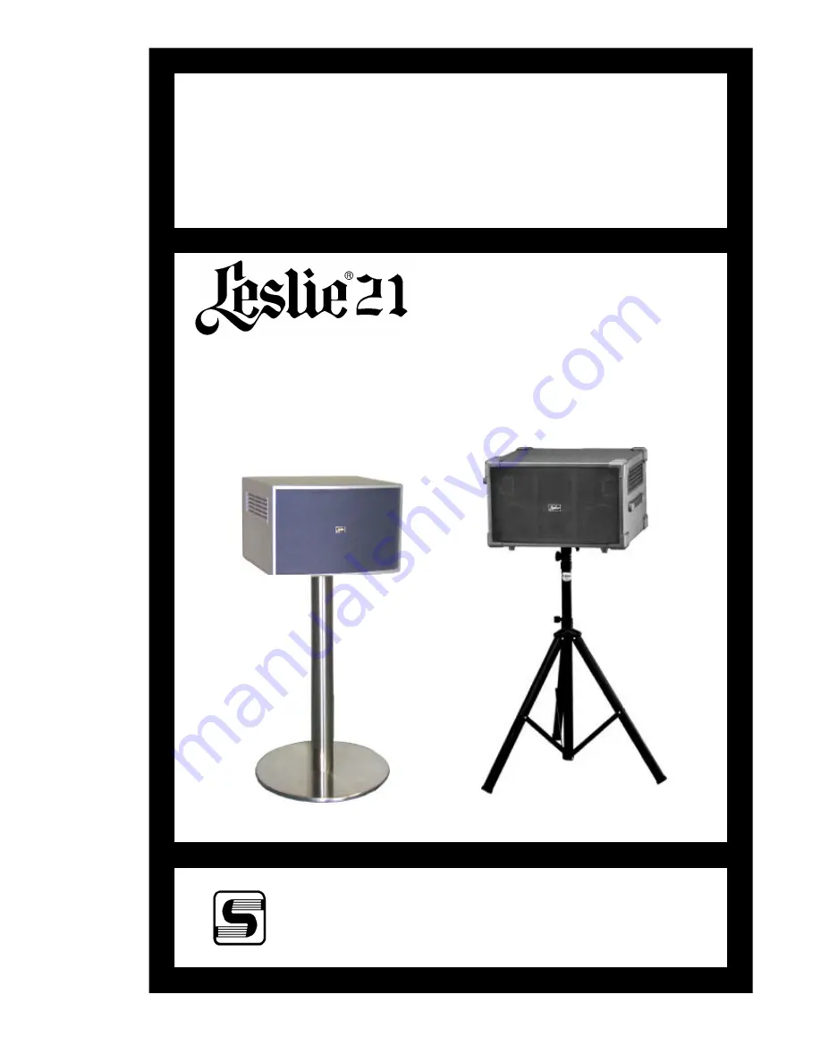
SERVICE MANUAL
SUZUKI MUSICAL INST.MFG.CO.,LTD.
25-12,RYOKE 2-CHOME,HAMAMATSU, JAPAN
~HA<O>
Dec.2002
CAUTION !
see safety notice inside
LESLIE 2102
(SILVER)
LESLIE 2101
(BLACK)
Rotary Unit
Units shown with optional stands.
Page 1: ...CE MANUAL SUZUKI MUSICAL INST MFG CO LTD 25 12 RYOKE 2 CHOME HAMAMATSU JAPAN HA O Dec 2002 CAUTION see safety notice inside LESLIE 2102 SILVER LESLIE 2101 BLACK Rotary Unit Units shown with optional s...
Page 2: ......
Page 3: ...NARY L STATIONARY R HORN ROTOR ACOUSTIC LOWER ROTOR 2channel DSP ROTARY HORN 50W LOWER CH 50WX2 ROTARY HORN COMPRESSION DRIVERX1 13cm WOOFERX2 5cm TWEETERX2 VOLUME STA L STA R ROTARY OVERDRIVE 8 POSIT...
Page 4: ...Relay Q1 Q2 RL1 5 ROTBASS MUTE ON OFF Q6 Q7 ROTBASS LEVEL VR5 VR4 OVER DRIVE COM 0 1 8 SW1 MEM D1 D2 D3 SW2 FUNC SEL SW3 PRESET SELECT COM 1 COM 2 SW5 VALUE Rotary Encoder ROT IN VOLUME VR1 SW4 FUNCT...
Page 5: ...e cabinet on it s side which has the four 4 rubber feet installed on a flat surface Unfasten the four 4 machine screws from the unit as shown in Figure 2 d REMOVAL OF MOTOR ASSEMBLY 1 Remove the Rotar...
Page 6: ...ion a 4 Remove the speaker grille by gently pushing the grille out from the inside of the cabinet 1 Remove the Speaker Grille by following the procedure outlined in Section g 2 To remove the 5cm speak...
Page 7: ...Line out Level STA L VOL Max 400Hz SINE WAVE 1Vrms LES11PIN 2 STA L OUT JACK b Stationary Rch Line out Level STA R VOL Max 400Hz SINE WAVE 1Vrms LES11PIN 3 STA R OUT JACK c Rotary Line out Lch Level R...
Page 8: ...P WR HZ100 B WR HZ118 C WR HZ100 MI WR HZ100 MP BLK BRN Rch Lch BLK VIO Part No Volts Voltage Select Plug Secondary Primary WR HZ118 B 3P 4P 2P 8P 5P 5P 10P 3P 15P 10P 8P 10P 6P 5P 15P 2P 10P 9P J204...
Page 9: ...10 1 GRN 15V 4 BLK Tweeter Rch 6 J103 3 BLK AG J106 1 AC INLET L BLK AC INLET 7 NC AG 2 NC 8 J110 5 ORG 15V 3 AC INLET N WHT AC INLET J304 1 J205 1 RED EFH 237A J107 1 Power Sw BLK Send L 2 NC 2 Power...
Page 10: ...A 2 NC DG CN2 1 MOTOR MOTOR 3 J301 3 WHT SWH 492A L OUT 2 4 J301 4 SHIELD AG 3 5 J301 5 RED R OUT 4 6 J301 9 WHT SUB L OUT 5 7 J301 8 SHIELD AG 6 8 J301 7 RED SUB R OUT 7 9 NC DG 8 J203 1 NC 5V 9 2 J3...
Page 11: ...101 2102 7 PRINTED WIRING BOARD ASS Y LIST FUNCTION PWB NAME PART No POWER SUPPLY AMPLIFIER PWH 68A 00218 28256 PREAMP PANEL SWITCH SWH 492A 00225 40296 CPU CONTROL EFFECT EFH 237A 00223 42201 1 3 3 3...
Page 12: ...K C24 3p R27 1W 0 22 R28 1W 0 22 C19 2 2 50V R24 56K R25 1800 C22 33 16V C23 100 50V R26 1 2W 100 C25 10 50V C27 0 1 50V R33 1 2W 4 7 C26 0 1 50V R31 1 2W 4 7 3 4 RL2A AJW5511 6 5 RL2B AJW5511 B B 1 2...
Page 13: ...L IN L IN R IN STA R STA L STA R STA L VR5 5k C62 2 2 50 MSR ROT BASS ADJ ROTBAS ROTBAS R54 4700 R36 4700 R43 4700 R42 4700 R44 4700 R45 10k Q6 2SC2878 R60 4700 R59 4700 ROT R ROT L ROT R ROT L ROT IN...
Page 14: ...9 26 A10 23 A11 25 A12 4 A13 28 A14 29 D0 13 D1 14 D2 15 D3 17 D4 18 D5 19 D6 20 D7 21 CE 22 OE 24 Vcc 32 GND 16 A15 3 A16 2 A17 30 A18 PRG 31 Vpp 1 U4 SST27S010 70 3CPH MA0 MA1 MA2 MA3 MA4 MA5 MA6 MA...
Page 15: ...D10 FD4 C19 0 1u C20 0 1u NC NC NC C21 0 1u FD0 FD1 FD2 FD3 FD4 FD5 FD6 FD7 FD8 FD9 FD10 FD11 FD12 FD13 FD14 FD15 FD14 FD13 FD12 FD11 FD15 R48 2 2 1 4W VCC C32 10u 50V C51 0 1uf VCC VCC C22 0 1u NC C2...
Page 16: ...VAN C69 100u 16V C15 0 1u C31 10u 50V C16 0 1u C70 100u 16V R45 1000 5VAN R16 100 R17 100 NC NC NC NC 5DA C76 68P C77 68P NC LRCK BCLK AX1 AX2 C78 1000u 6 3V C79 1000p C80 1000p C81 1000p C82 1000p R4...
Page 17: ...h or Part No Only Use of another battery may present a risk of fire or explosion Battery may explode if mistreated Do not recharge disassemble Collect used battery promptly Keep away from childern Do...
Page 18: ...ency in the DSP The HF is being returned via J301 3 as the Rotary Horn signal through BPF circuit U3B AMP circuit U3A and VR6 and it is supplied to POWER AMP via J302 1 The LF signal is changed into t...
Page 19: ...he transformer Each three lines apply to the power amplifier 12 V 5V regulator IC and 24V for Motor Power supply The devices between the transformer volume line and the rectifier diode PSW 1 2 3 are P...
Page 20: ...030 00452 40153 00613 53025 00452 40147 Cabinet Total Ass y 2101 2102 Rear Panel Ass y Power Transformer EPH 115 Rotary Horn Ass y Speaker 5cm Speaker 13cm Speaker Cushion XE Tapping Screw TYPE A Trus...
Page 21: ...345 01007 00443 05033 00453 40142 00451 40310 00452 40152 1 2 3 4 5 6 7 8 9 Rotary Horn BASE Horn Driver Spindle Hub Set Rotary Horn 514 140436 Motor FY815 SD3 Motor Pulley 22 Rubber Gromment G 85 Spa...
Page 22: ...00443 05032 00443 05016 00443 05017 WR HZ100 A WR HZ100 B WR HZ100 C WR HZ100 D WR HZ100 R WR HZ100 T WR HZ100 W WR HZ100 MP WR HZ100 MI WR HZ118 B WR HZ118 C 1 2 3 4 5 6 7 8 9 VOLTAGE SELECT PLUG 1 2...