background image


3


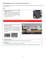
Laser Control Panel and Functions


The Status LEDs 


Status LED – red – indicates the laser is powered on. 


Low Battery LED – red - blinks if the battery is low and needs charging. 


Charging LED – yellow – lights when the rechargeable battery is charging (see 
Figure 3). 


The On/Off Button 

Press the 

ON/OFF

 button once to turn it on and press and

 hold

 to turn it off.  The 

I/O LED will illuminate when the power turns on. 
 

L-702SP Scan button 

Power the L-702SP on and press the 

SCAN

 button to turn on the turret laser rotation 

and create a scan plane.  Press it again to turn it off.   

Note:


The Pentaprism in the turret will need to be pivoted into place to create the 

scan plane.  

See

  Switching L-702SP Turret into Scan Mode  on 

Page  19 

for 

instructions

.


A/C Connector 

 
The L-702 comes with a rechargeable battery.  The connector is shown below. 


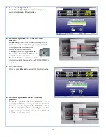
Pitch/Roll Adjustment Knob 

The adjustment knobs use differential micrometers, allowing both coarse and fine functions.     


Coarse Adjustment – tighten the set screw to disable the fine adjustment. 


Fine Adjustment –  loosen the set screw to enable the fine adjustment, 
which is 12 times finer adjustment resolution. 


Figure 4– Differential Micrometer 


Figure 3– L-702/L-702SP Control Panel 


Summary of Contents for L-702

Page 1: ......

Page 2: ...icles of equipment manufactured by other companies and limited by a warranty extending for less than one year In such an event the more limited warranty applies to said instrument or article of equipm...

Page 3: ...11 Qualifying the L 702 Laser Beam to a Spindle AOR 12 The NORMIN Method 12 Adjustments 13 Pitch Yaw Adjustment 13 Hardware Requirements 13 Spindle Qualifying Procedure Using Lathe9 Software 14 Setup...

Page 4: ...quick alignment check in 20 minutes and get full alignment data in 30 40 minutes on most machines Easy Laser and target mount directly into the spindle and tailstock respectively allowing the entire...

Page 5: ...n milling axes Built in levels on the sides provide easy indexing when inverting for error correction readings A 0 50 in 12 7 mm mounting stud simplifies fixturing and can be removed to adapt the unit...

Page 6: ...er rotation and create a scan plane Press it again to turn it off Note The Pentaprism in the turret will need to be pivoted into place to create the scan plane See Switching L 702SP Turret into Scan M...

Page 7: ...4 L 702 L 702SP Laser Dimensions...

Page 8: ...utlined in Appendix C beginning on Page 31 Figure 6 T 261 Four Axis Target The R 358 Computerized Interface The R 358 Computer Interface provides high accuracy resolution is 00001 in or 0 0005 mm for...

Page 9: ...r beam A V angular value indicates the back of the target is higher than the front of the target A V center value indicates the target is lower than the laser beam A V angular value indicates the back...

Page 10: ...ck AOR Hardware Mounting Both the L 702 L 702SP Laser and T 261 Target have a standardized 4995 in 12 69 mm mounting stud that simplifies fixturing and that can be removed to adapt the unit to custom...

Page 11: ...rget is purchased separately it should be calibrated before use This can be done at the factory or on site using the A 807 Calibration Fixture and Read8 available for purchase from Hamar Laser The pro...

Page 12: ...s to the computer through the USB port Installing the Driver 1 Insert the Flash drive in an available USB port 2 Select My Computer locate the REMOVABLE DISK icon and click to open it 3 Select the US...

Page 13: ...nal splitter cable Make sure to screw in the flat head screws to securely hold the connector in place INPUT Front Back Note The R 358 power is turned on by the software when you click any of the Lathe...

Page 14: ...s which are always there After the alignment it is always a good idea to re qualify the laser to its mounting stud which puts the L 702 angular adjustments in the center of their adjustment range To r...

Page 15: ...fixture is rotated 180 degrees to the INverted cable up or switch panel facing away from you position and a second set of readings obtained With a quick calculation the two sets of readings are averag...

Page 16: ...have a coarse and fine function Coarse Adjustment tighten the set screw to disable the fine adjustment Fine Adjustment loosen the set screw with the provided Allen wrench to enable the fine adjustment...

Page 17: ...k and tailstock spindles Mount the laser in the headstock spindle and the target in the tailstock or the T 230 Target Stand Both the laser and target should be in the NORMal position The NORMal positi...

Page 18: ...y 5 seconds Ensure the bubble level is in the center of the circle Note Do NOT rotate the laser in the chuck Always rotate the laser and spindle TOGETHER as one unit 7 Click RECORD Click or press Reco...

Page 19: ...button will turn gray Click Offset again to turn them back on 10 Adjust the V and H Angular slope adjustments Turn the Pitch and Roll adjustment knobs until the Slope values in the Step 2 display are...

Page 20: ...17 12 See the Lathe9 Manual for information on how to check straightness of the lathe bed guideways and parallelism of the headstock to the guideways...

Page 21: ...can measure straightness and squareness of a cross slide axis or of a multi turn machining axis To measure a cross slide or a machining axis of a multi turn machine the A 1519 2 4ZB Single Axis Wirele...

Page 22: ...beam that emits from the side of the spindle which is then rotated to create the scanning laser plane The flip mechanism is controlled by a screw in the top of the spindle Use a standard screwdriver...

Page 23: ...oss slide using custom fixturing or the magnetic base that comes with the target Adjust the height of the target so the laser plane is in the middle of the window by rotating the turret by hand to see...

Page 24: ...xis and Take Measurements Move the cross slide axis a short distance and note the value on the readout Write down the readings and the distance traveled Any deviations from zero are a measure of squar...

Page 25: ...Page 19 2 To Measure X Axis Straightness in C and Squareness to C Attach the A 1519 2 4ZB Target to the spindle using custom fixturing or the magnetic base that comes with the target Adjust the heigh...

Page 26: ...have to be mounted to the side of the headstock spindle and bucked in to the Y axis with the A 1519 2 4ZB mounted on the side of the X axis spindle Alternatively the L 742 Dual Scan or L 743 Triple Sc...

Page 27: ...tall the T 261 4 Axis Target into the machining spindle Move the machining spindle until the T 261 is close to the L 702SP within 4 in 100 mm In Lathe9 take data in Step 3 see the Lathe9 Manual by mov...

Page 28: ...25 7 Lathe9 Step 3 and Results Screen...

Page 29: ...involved in bore alignments True Bore Center Target Center and Laser Reference Centerline If mounting fixtures were perfect the Target Center would be located at the True Bore Center and if perfectly...

Page 30: ...he readout are also rotated Therefore although the Target Center appears to be to the right of and lower than the Laser Beam Center in Figure 20 the vertical readings will be positive and the horizont...

Page 31: ...ng errors The word is a contraction of NORMal INverted which briefly describes the method To take NORMIN readings the laser and target fixtures are set in the NORMal position cable down and the readin...

Page 32: ...et To measure both the angle and center a two axis target with an angle module the T 212 or a four axis simultaneous target such as the T 261A is required If the laser is being qualified to its own mo...

Page 33: ...002 would be the vertical angular set point Use the two vertical angular readings to calculate the set point for vertical angle The horizontal angle set points would be calculated in the same way 4 Ad...

Page 34: ...nually or calibration may be done automatically by the program Calibration Setup 1 Mount the laser and target Note Figure 22 shows the target mounted in the Hamar Laser A 807 fixture stand In order to...

Page 35: ...e horizontal axes see Figure 22 If working with a fixture that has a horizontal micrometer there is no need to rotate the target see Figure 23 Figure 25 Channel Port Selection Screen Figure 26 Calibra...

Page 36: ...record the reading 5 Re zero the target Turn the micrometer 025 in one full turn in the direction opposite that in Step 3 You are now ready to record the next calibration factor Note If using the Mod...

Page 37: ...025 in one full turn moving in the same direction as Step 1 This corresponds to Step 2 on the Calibration Screen The displayed reading should be close to 025 for the positive factors and close to 025...

Page 38: ...is connected to R 358 Check connectors for broken pins or wires Check for kinks in the cables Ensure laser is powered on Ensure laser beam is bright use white paper to see beam Ensure the beam is hit...

Page 39: ...the type intended for nail polish removal NOTE When cleaning precision optics even with the best quality optical cleaning tissue use gentle pressure to avoid scratching the surface or damaging the op...

Reviews: