16
9.
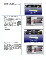
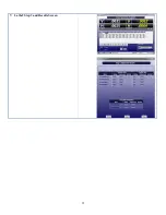
Click RECORD.
Click or press
Record
to record the NORMal
value.
Lathe9 automatically calculates display offsets so
you can adjust the two
angular
adjustment axes to
zero instead of the calculated Set Point.
Note:
While it is not recommended, if you want to see
the raw values, click the Offset button to turn the offsets
off (the green ON
button will turn gray). Click Offset
again to turn them back on.
10.
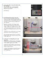
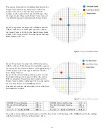
Adjust the V and H Angular (slope) adjustments
Turn the Pitch and Roll adjustment knobs until the
Slope values in the Step 2 display are within
±.0001 in/ft (0.012 mm/m) of zero.
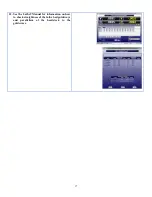
Here are the L-702 V and H
Angular
(
Slope)
values
in or close to tolerance.
Note:
There are no center adjustments with the
L-702 since any small centering errors, will be
averaged-out by using the NORMIN procedure in Step 5.
11.
Repeat Steps 6-10 to verify the laser is aligned to the spindle rotation axis.
Summary of Contents for L-702
Page 1: ......
Page 7: ...4 L 702 L 702SP Laser Dimensions...


