Operators Manual
Operation, Maintenance and Service
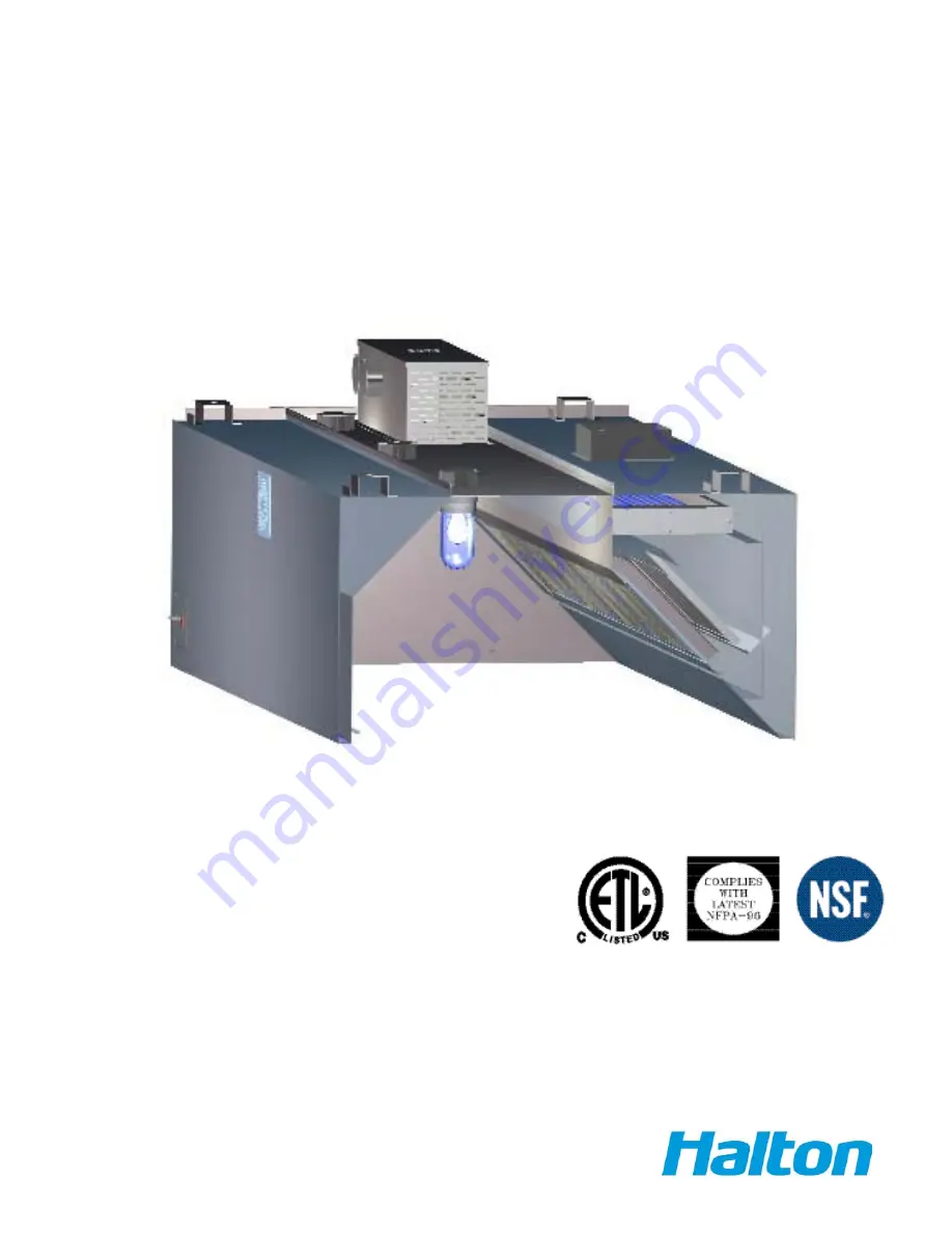
Capture Ray
TM
Hoods
Model: KVE-UV, KVC-UV, KVW-UV
Page 1: ...Operators Manual Operation Maintenance and Service Capture RayTM Hoods Model KVE UV KVC UV KVW UV ...
Page 2: ...t hanging weight Do not lift exhaust hoods from their end panels Lift from four corners All exhaust hoods and control panels are fitted together and factory tested prior to shipping for alignment and operation Duct Connections Duct connections meet NFPA 96 of applicable local codes Size of connection is indicated on exhaust hood drawing Connection to be made after exhaust hood is hung PROPER LOCAT...
Page 3: ...THERS 18 GA MAT L BY OTHERS EXHAUST DUCT EXHAUST COLLAR CONTINUOUS LIQUID TIGHT WELD HANGER BRACKET DETAIL ALL THREAD TURN BUCKLE HANGER BRACKET EXHAUST DUCT PER CODE SUPPLY DUCT ALTERNATIVE WELD LIQUID TIGHT CONTINUOUS IMPORTANT NOTE SUPPLY DUCT SUPPLY DUCT MAY BE ATTACHED TO SUPPLY COLLAR WITH SHEET METAL SCREWS OF POP RIVOTS AND SEALED WITH DUCT TAPE SCREWS RIVOTS ARE NOT TO INTERFER WITH THE O...
Page 4: ...annel on starting from one end and going to the other A Splice Strip Insert splice strip over bottom front edge first then over top front of the hood Secure to top of the hood by welding or sheet metal screws supply plenum only B Secure to top of the hood by welding then over top sides bottom sides first Insert splice strip over Splice Strip U Channel Holds two backs together Clamp the two backs t...
Page 5: ...a Velocities of make up air should be kept to a minimum especially near the exhaust hood perimeter CAUTION High make up air velocities will distrub smoke capture Many codes call for a number of air changes per hour This should be reviewed with the entire ventilation requirements of the facility METHOD OF DETERMINING AIRFLOWS The air flow through the Capture RayTM hoods in determined by using the t...
Page 6: ...tween ambient air and the exhaust plenum the T A B Port reading AccuFlow installs in Capture Jet plenum for easy viewing and access The device shares an electrical circuit with the Capture Jet fan Photo 1 Halton AccuFlow Photo 2 AccuFlow PressureTaps Exhaust airflow rate is determined in the same fashion as other Halton Capture Jet hoods each hood has a unique K Factor dependent upon model The act...
Page 7: ...airflow K Factors have been determined by Halton Research and Development personnel Bluetooth capability also allows an Authorized Service Agent to determine the airflow of an exhaust hood on site if an alarm is present This information can be conveyed to Halton personnel for troubleshooting Alarms Alarms are enabled when design airflow is above or below ten percent of design airflow An alarm is v...
Page 8: ...ccuFlow device Loose or improper electrical connections Verify or reconnect electrical connections Low airflow alarm Not reaching design airflow Plastic tubing disconnected from Accuflow device or TAB port Broken plastic tubing Dirty or plugged TAB port in exhaust plenum Increase fan speed Reconnect Replace tubing Clean TAB port Failure Bad Device Replace ...
Page 9: ...shed by use of a thermal fusible link in the exhaust collar and detection line above the appliances If the fusible link should activate it would close the fire damper if supplied and automatically release the suppression agent NOTE Depending on the type of cooking equipment covered an additional surface fire protection system is typically required In the event of a fire the surface fire protection...
Page 10: ...it by the correct model number including perfix and suffix letters and numbers and serial numbers if shown The model plate affixed to the unit contains this information and is mounted on the inside of the hood wall REGULAR MAINTENANCE ENSURES PEAK PERFORMANCE CLEANING EXTERIOR STAINLESS STEEL Normal soil may be removed with a stainless steel detergent and warm water applied with a cloth NOTE Remov...
Page 11: ...sure the unit is turned off at the control panel Remove the KSA grease extractor and clean the interior sections of the exhaust plenum where there is any grease build up Gently wipe any grease off the UV lamps Monthly The Capture RayTM hood should be inspected regulary The UV tube frames and controls should be verified for proper operation and cleaning Check to ensure that all indicator lights are...
Page 12: ...et the 10 000 hour clock it is necessary to use the keypad to reset the timer DISPLAY CAUSE SOLUTION Error A lamp has failed the voltage to the lamp is too low or the lamp ballast has failed Check line voltage Replace UV Lamp Replace lamp ballast if needed No Fan Either the fan is at a lower speed or belt has broken Either a KSA filter is not in place in the hood or the cassette access door is ope...
Page 13: ...15 When switch is closed UV shuts off immediately without delay UV is the only output affected After Flow Alarm Delay time buzzer sounds and display scrolls No Fan If switch is open again thereafter for at least 1 second UV lamp output resumes operation and error is cleared 1 second delay to avoid contactor flickering when pressure is unstable UV Lamp Failure Switch Normally Closed switch stays op...
Page 14: ... alarm buzzer Total to display the total number of hours of UV operation Clean to display the number of hours of operation since last UV cleaning There are six LEDs from left to right UV lamps ON UV access door open M lit when miscellaneous input is activated No Fan lit when insufficient airflow in the system is detected by pressure switch Fire Maintenance If UV Lamp Failure option is enabled and ...
Page 15: ...TATISTICS Two types of statistics are recorded Total Hours Of Operation and Total Hours Since Last Cleaning These are simply displayed as a number of hours If this exceeds 999 hours then the dis play rounds to the nearest 10 and displays as kilo hours with a decimal For example 517 hours is displayed as 517 whereas 1517 hours is displayed as 1 52 Statistic is viewed by pressing either Total or Cle...
Page 16: ...up if the Clean key is pressed the unit will reset all parameters to their default values MAXIMUM UV CLEANTIME Maximum time allowed in kilo hours before UV Service LED lights Parameter name P01 Allowed values 0 01 to 9 99 Factory default 1 60 MAXIMUM UV OPERATINGTIME Maximum time allowed in kilo hours before UV Service LED lights Parameter name P02 Allowed values 0 01 to 9 99 Factory default 9 99 ...
Page 17: ...eter name P05 Allowed values 0 off never sounds alarm to 999 Factory default 30 REMOTE ON OFF Enables or disables the remote On Off switch If enabled keypad On Off no longer controls the unit except to program Low level When enabled a remote closed contact will mean On and an Open contact will mean Off Parameter name P06 Allowed values 0 Disabled 1 Enabled Factory default 0 UV LAMP FAILURE DETECTO...
Page 18: ...GUIDE INOPERATIVE PROBLEM CAUSE SOLUTION Exhaust fan and UVC lamp will not function Control Panel Message No Fan or Error Field Wiring or Breaker Verify field wiring for proper connections Check fuse at control panel Fan on but no UVC lamps Control Panel Message No Fan or door OPEN UV door open Pressure switch malfunction Close door Check wiring Check air tube for blockage Replace pressure switch ...
Page 19: ... EXHAUST PLENUM CLIP C EYE BOLT CLIP B CLIP A COLLAR FIRE DAMPER 2 LINK 3 LINK 1 LINK D 1 REMOVE GREASE FILTERS 2 UNRAVEL S S CABLE AT CLIP A 3 FEED LOOSE END OF CABLE THROUGH EYEBOLT AT CLIP B THEN BACK THROUGH EYEBOLT AT CLIP C 4 HOLD FIRE DAMPER IN MAXIMUM OPEN POSITION TO ATTACH LINK AT POINT D 5 CLOSE S HOOKS AS REQUIRED 6 FOR FINAL ADJUSTMENT OF FIRE DAMPER TO ASSURE MAXIMUM OPEN POSTION USE...
Page 20: ...ce charges miscellaneous tools material charges and labor charges resulting from inaccessibility of equipment will not be paid by Manufacturer This LIMITED WARRANTY SHALL APPLY ONLY to products that have been installed and maintained in accordance with the installation and Care Instruction Manuals Purchaser shall be solely responsible for adhering to the instructions and procedures set forth in th...