16
221992D
4.13 Water & Gas connections
Replace fan access door, heat shield and control box.
Note: When replacing the fan access door make sure the lip at
the top of door fits into and behind the slotted bracket located at
the top of the boiler.
As there are two casing height options, the control box height
and the heat shield may have to be adjusted to suit your
requirements.
Complete the water connections to the boiler.
Fill, vent and flush the system.
Check for any water leaks and put right.
Make the gas connection to the service cock, at the lower left
hand side of the boiler, see diagram 1.1.
The whole of the gas installation, including the meter, should be
inspected, tested for soundness and purged in accordance with
the current issue of BS6891.
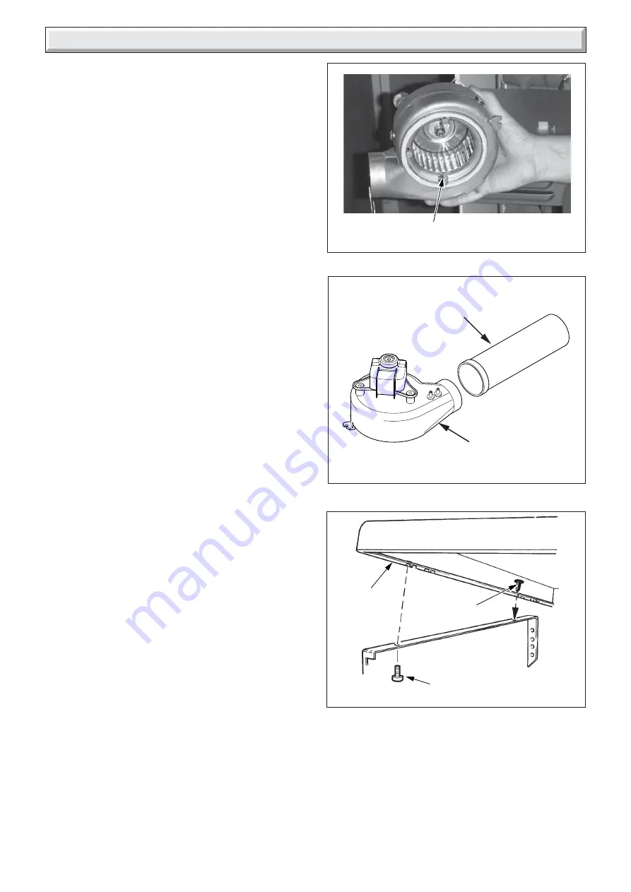
4.14 Top Casing
Refer to diagram 4.21.
Fit two plastic pegs, one on each side, in the holes on the top
casing. The plastic pegs are a tight fit and are best pushed home
with a flat faced tool.
Secure front of top casing with the screws provided.
4 Installation
Diagram 4.21
TOP CASING
9865
SCREW (2)
PLASTIC
PEG (2)
10149
Diagram 4.20
FLUE DUCT
EXTENSION PIECE
FAN
Diagram 4.19
SECURING
LUGS


