22
2000225116B
8.4 Service Checks
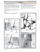
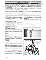
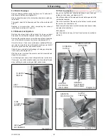
Inspect the ignition and sensing electrodes and clean and
replace as necessary, see diagram 8.12.
Check the condition of the side and rear insulation panels in the
combustion chamber.
Check the condition of the seals on the boiler access door and
the combustion chamber cover.
Examine the flue hood and terminal to make sure they are clean
and clear of obstructions.
Refit all parts.
Light the boiler and carry out functional tests as described in
section 6.
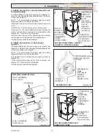
BURNER
GRAPHITE
COATED NUT(2)
SUPPLY
FEED PIPE
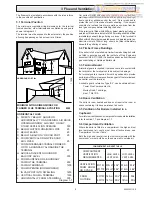
8.2 Boiler Flueways
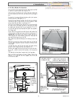
Remove flueway baffles noting that there are 3 centre and 2
side flueway baffles, see diagram 8.8.
Place a sheet of paper in the combustion chamber to catch any
flue debris.
Thoroughly clean boiler flueways and fins with a suitable stiff
brush.
Replace in reverse order, after completing the relevant
instructions in sections 8.3 and 8.4.
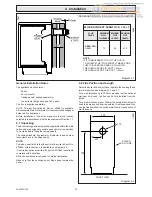
8.3 Burners and Injectors
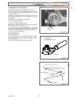
Remove the screws and nuts securing the burner support
bracket to the combustion chamber cover, see diagram 8.9.
Remove the graphite coated nuts on the supply feed pipe at the
rear of the burner to release the burner, see diagram 8.10.
Clean the burner. Use a vacuum cleaner or suitable stiff brush
(not wire) to clean the burner thoroughly, making sure that all
the burner ports are clear and unobstructed.
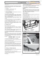
Check the burner injector for blockage or damage and replace
if necessary, see diagram 8.11.
With the burner removed the injector can be inspected and
cleaned as necessary.
For cleaning do not use a wire or sharp instrument on the hole.
If removed, use a little suitable sealant on the external thread
when refitting to make sure a gas tight seal is made.
Diagram 8.8
FLUEWAY
BAFFLE
HEAT
EXCHANGER
8 Servicing
Diagram 8.10
Diagram 8.9
BURNER SUPPORT
BRACKETS
SCREWS &
NUTS (2)
SIDE
FLUEWAY
BAFFLE
HEAT
EXCHANGER
IGNITION
ELCTRODE
(Black cable)
SENSING
ELECTRODE
(White cable)


