Supplied By www.heating spares.co Tel. 0161 620 6677
10
12
Expansion Tank:
The expansion tank must be of the diaphragm
type and should be connected close to the inlet side of the pump.
The expansion vessel must suit the volume of the system -
BS5449:1:1977, clause 25.
Safety Valve:
A safety valve complying with the requirements of
BS759 must be fitted to the flow pipe as near as possible to the boiler
with no restriction in the flow before the valve. (Refer to Fig. 12)
The valve should be fitted by a horizontal or vertically upwards
connection and accessible for testing.
The valve should be so positioned so that any discharge of steam
or water cannot cause any harm to occupants or electrical
installations.
Pressure Gauge:
A pressure gauge with a range of 0-4 bar
must be fitted so that it is visible to the person filling the system.
3.7.2
SEALED SYSTEMS
The system pressure should be not less than the static height, this
being the highest point in the system above the expansion tank.
The expansion vessel has to be suitable to accommodate the
change in volume of the water in the system when heated
between 10°C to 110°C. See BS5449:1 for further information.
Hot Water Cylinder:
The cylinder used should be of the
indirect type, suitable to operate at a total pressure of 0.35 bar
(5 lb/in
2
) plus the pressure at which the safety valve is set.
Do Not Use A Single Feed Indirect Cylinder.
Filling Point:
The system must be provided with a low level filling
point fitted with a stop cock. The method adopted for filling the
system should comply with local Water Authority regulations.
Provisions should be made for replacement of system water losses
by using a make-up vessel which must be fitted above the highest
point in the system, or by pre-pressurising the system.
Refer to BS5376:part 2:1976 clause 14.3.5.
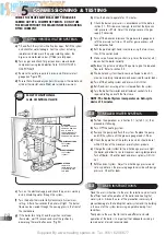
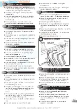
The primary flow and return pipework between the boiler and the
hot water cylinder must be 28mm and be connected to the 28mm
connections, the flow to the top manifold and the return to the
bottom manifold. (Refer to Fig. 11)
‘Street’ elbows,
must
be used for the 28mm gravity connections
to the boiler to provide adequate clearance for fitting the right
hand inner case.
The central heating flow
must
be connected to the 22mm
connection on the top manifold.
The central heating return
must
be connected to the 22mm
connection on the bottom manifold to ensure correct operation of
the integral injector system.
Gravity systems require a minimum circulating head of 1m where
there is no horizontal pipe run. An increase in circulating head of
0.5m is required for each 1m of horizontal run.
Note:
Gravity runs near the minimum circulating head may
result in prolonged cylinder recovery.
Note:
It is recommended that when used on a gravity domestic
hot water application a Honeywell “C Plus” plan or equivalent is
fitted to the system to give suitable control over the domestic hot
water temperature. The cylinder thermostat should be set
NO
higher than 60°C. The Honeywell “C Plus” will allow the pump
overrun to operate (should it be necessary) without warming the
radiators when the domestic hot water only is on. The bypass
should have the same water volume, 7 litres minimum, but should
NOT
incorporate any radiators. The flow sensing temperature is
limited to 6O°C in the gravity mode, when the CH pump is off. This
is to prevent the DHW cylinder from overheating.
VOLUME OF WATER IN APPLIANCE = 3.0 litre.
Vessel Charge &
Initial System
bar
0.5
1
1.5
Pressure
psi
7.3
14.5
21.8
For expansion vessel capacity,
multiply system volume by:
0.0833
0.109
0.156
3.7.1.2
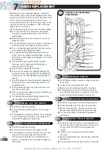
COMBINED PUMPED
SEALED WATER SYSTEM
Halstead Boilers manufacture a Sealed System Pod that
fits directly below the appliance. This incorporates an
expansion vessel, pump, pressure relief valve with
interconnecting pipe work.
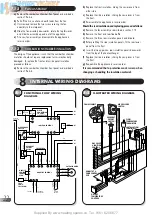
AUTOMATIC
AIR VENT
HOT WATER
CYLINDER
FILL PIONT
PUMP
SAFETY
VALVE
EXPANSION
VESSEL
DRIAN
COCK
PRESSURE
GAUGE
BY -PASS WITH
LOCKSHIELD VALVE
WATER CONTENT
7 LITRES MINIMUM
FLOW
RETURN
HEATING
CIRCUIT
AIR RELEASE
VALVE
NON RETURN
VALVE
MAKE UP BOTTLE:
Observe minimum
static head requirements
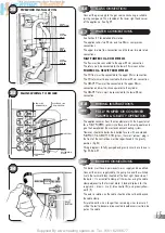
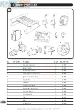
The combined heating and hot water flow must be connected to
the top manifold, use either the 22mm or 28mm connections.
The open vent may be connected to the un-used connection on
the top manifold. (Refer to Fig. 10)
The combined heating and hot water return must be connected to
the bottom manifold, use either the 28mm or 22mm connections.
The cold feed may be connected to the un-used connection on the
bottom manifold.
3.7.1.1
FULLY PUMPED
CH & GRAVITY DHW SYSTEMS


