PAGE 4
98593C (Rev. C - 01/15)
WCFS*G*L*R WC8AFSQ*1G WC8AFSQ*2GJO
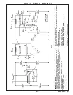
HANGER BRACKETS & TRAP INSTALLATION
1
) Remove hanger bracket fastened to back of cooler by
removing one (1) screw.
2) Mount the hanger bracket and trap as shown in Figure 2.
NOTE:
Hanger Bracket MUST be supported securely. Add fix-
ture support carrier if wall will not provide adequate support.
IMPORTANT:
•
5-1/2 in. (140mm) dimension from centerline of unit to
centerline of trap must be maintained for proper fit.
Anchor hanger securely to wall using all mounting holes.
3) Install straight valve for 3/8" O.D. unplated copper tube.
INSTALLATION OF COOLER
4) Hang the cooler on the hanger bracket. Be certain the
hanger bracket is engaged properly in the slots on the
cooler back as shown in Figure 2.
5) Loosen the two (2) screws holding the lower front panel at
the bottom of cooler base and two (2) screws at the top.
Remove the front panel and set aside.
6) Connect water inlet line--See Note 4 of General Instructions.
7) Remove the slip nut and gasket from the trap and install
them on the cooler waste line making sure that the end of
the waste line fits into the trap. Assemble the slip nut and
gasket to the trap and tighten securely.
START UP
Also See General Instructions
8) Stream height is factory set at 35 PSI. If supply
pressure varies greatly from this, adjust screw, ac-
cessible by removing front panel (Item 7, Fig. 3). CW
adjustment will raise stream and CCW adjustment will
lower stream. For best adjustment, stream should hit
basin approximately 6-1/2” (165mm) from bubbler.
9) Replace the front panel and secure by retightening
four (4) screws.
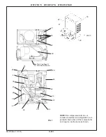
PUSH BAR MECHANISM
LEGEND
A) Note: Water flow direction
B) Adjust this screw to eliminate mechanism “Free Play” or continuous
flow from bubbler conditions. (See ADJUSTMENT PROCEDURE)
C) Stream height adjustment (see note #8)
Water Valve Mechanism - ADJUSTMENT PROCEDURE:
- Turn adjustment screw (Item 9) “Counter-Clockwise” until water flow from bubbler starts.
- Turn adjustment screw “Clockwise” until water flow stops, THEN turn an additional 1/2 turn.
NOTE:
Adjustments stated above are viewed from underneath unit (bottom side of dispenser
panel Item 1)
NOTE:
If continuous flow occurs at the end of the compressor cycle, turn cold control (Item
46) counterclockwise 1/4 turn.
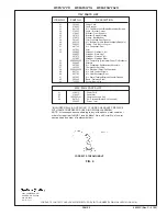
ITEM NO.
PART NO.
Panel - Bottom Dispenser
Kit - Push Bar/Pivot Blocks/Bumpers/Rivets
Kit - Pushbars (Front & Sides)/Inserts/Nuts
Kit - Front/Side Pushbar Bracket/Screws
Panel - Right Side
Panel - Left Side
Panel - Front Push
Screw - Regulator Brkt. Mtg.
Screw - Shoulder x 1/2" Lg.
Kit - Regulator/Holder/Nut
Bracket - Regulator Mounting
Hex Nut
26588C
98537C
98895C
98789C
See Color Table
See Color Table
See Color Table
75502C
70935C
98531C
23003C
40045C
Item No. 5
Part No.
(w/o hole)
COLOR TABLE
Platinum Vinyl
Stainless Steel
Almond Vinyl
Slate Vinyl
26644C
26637C
26636C
26646C
26659C
26652C
26651C
26661C
26614C
26607C
26606C
26616C
PANEL COLOR
1
2
3
4
5
6
7
8
9
10
11
12
DESCRIPTION
26629C
26622C
26621C
26631C
26599C
26600C
26601C
26602C
Item No. 5
Part No.
(with hole)
Item No. 6
Part No.
(w/o hole)
Item No. 6
Part No.
(with hole)
Item No. 7
Part No.
FIG. 3
6
4
3
4
7
3
3
3
3
4
2
8
9 B
2
C
4
4
2
12
11
10
10
10
1
3
4
5
A


