


MAN1565-4
24
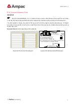
6.12
General Indicator Card
IMPORTANT
Note: The Cards BRD25GIB
–
A, B, C, D and E all have a common PCB. What sets them apart from each other
is not only the function they perform but how the componentry is loaded onto the card to perform that function.
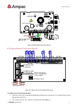
This Card indicates / displays the status of the inputs on the 16 Way Input Termination Board by way of Program
selectable tri-
coloured LED’s The function is identified on the front panel by slip in labels whose lettering must no
smaller than 3 mm.
Quiescent Current
: 3.6mA depending on the application
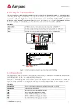
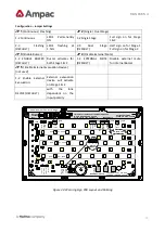
K2 Termination
Link
In
Out
Address
Switch
Set to 1
1
2
3
4
ON
C
N
1
C
N
2
CN1: Communications & 27V IN
from CN2 off the previous Front
Panel Card or CN9 on the Main Card
CN2: Communications & 27V OUT to Next Front Panel Card.
If Unsed the Termination Link Must be Inserted.
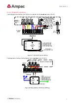
Top Card &
PCB Securing Clips
Bottom Card &
PCB Securing Clips
Figure 19: Front Panel Card Layout
Figure 20: Front Panel Card PCB Layout


