


MAN1565-4
17
6.7
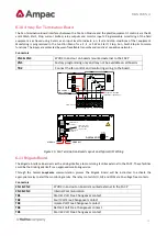
8-Way Relay Board
The Relay Board provides 8 programmable relays with 30VDC 1 Amp voltage free change over contacts for control or
monitoring purposes and comes fitted for internal or external FACP use.
The functionality and programming of the relays is similar to the relays on the main board of the FACP. By default the
relays default to Common Alarm functionality.
Protection
All terminal points are protected.
The board switches the relays as determined by the panel. The relays can be controlled by:
➢
Zones going to alarm
➢
Zones going to fault
➢
Zones Disabled
➢
Reset
–
relay is activated for 3 seconds when reset depressed
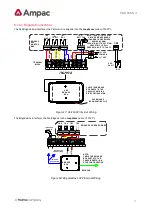
6.7.1
Internal Relay Board
Fit EOL Termination
Link 1 if Last Module
on Comms Bus
Address SW
SET to 1
Not used optional 27VDC
RS485 Control / 27VDC
Comms In
CN2
CN1
CN3
CN4
ON
+
-
TB8
TB7
TB6
TB5
TB4
TB3
TB2
TB1
SW1
O/P 8
N/C
COM
N/0
O/P 7
N/C
COM
N/0
O/P 6
N/C
COM
N/0
O/P 5
N/C
COM
N/0
O/P 4
N/C
COM
N/0
O/P 3
N/C
COM
N/0
O/P 2
N/C
COM
N/0
O/P 1
N/C
COM
N/0
1 2 3 4
O N
TB8
TB7
TB6
TB5
TB4
TB3
TB2
TB1
O/P 8
N/C
COM
N/0
O/P 7
N/C
COM
N/0
O/P 6
N/C
COM
N/0
O/P 5
N/C
COM
N/0
O/P 4
N/C
COM
N/0
O/P 3
N/C
COM
N/0
O/P 2
N/C
COM
N/0
O/P 1
N/C
COM
N/0
N/0 = Normally Open
COM = Common
N/C = Normally Closed
RS485 Control / 27VDC
Comms Out
Figure 11: Internal 8 Way Relay Board PCB Layout
Relay Connections
Terminal/s
Function
TB1 to 8 / 1, 2, 3
N/O = Normally Open
C = Common
N/C = Normally Closed
Relay 1 to 8


