5
A
B
D
C
B
C
B
B
A
D
F i g . 2 a
F i g . 2 b
A
B
C
C
A
B
B A S E F E E T
Legs are packed in carton box. Legs should be installed near to where the appliance is to be used, as they are not
secure for long transit. After unpacking the range, raise it about a foot to remove the bottom shipping skid. Keep the
unit raised to permit legs to be screwed into our couplings and lower it gently to keep any undue strain from the legs
and internal mounting hardware. It is strongly recommended that a pallet or lift jack be used rather than tilting.
F i g . 1 a
1) Remove the foot (A) from the cooker and
fi
x in the foot cover (D)
2) Secure the foot cover (D) with three bolts,
the three whashers and the three nuts (B)
into the bracket (C) which is positioned at
the rear of the kitchen
F i g . 1 c
1) Screw partially bolt (F)
into the base feet (G).
2) Insert base feet (G) into
the hole (Ha), move to the
hole (Hb) and screw com-
pletely bolt (F).
F i g . 1 b
1) Insert the bolt (A) into the bra-
cket hole and tighten the nut (B).
2) Insert the pin between the bra-
cket and the
fi
xing support (D)
and tighten the nut (B).
PRESSURE GAS REGULATOR INSTALLATION INSTRUCTION
Pressure gas regulator is supplied with the appliance. It is stored in the oven.
As show in
F i g u r e 2 a
, unscrew B part from C part.
Screw B part into A part (
F i g . 2 a
). Please use a proper gasket, for this connection.
As show in
F i g u r e 2 b
, screw A+B part into part C.
M A J E S T I C
P R O F E S S I O N A L
M A J E S T I C PAW L I O N F E E T
Summary of Contents for UP60
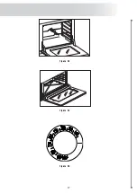
Page 17: ...17 Figure 24 Figure 25 Figure 23...
Page 29: ...29 MULTIFUNCTION MODELS ONLY Big Solid Top Burner...
Page 30: ...30 UP90MP...
Page 31: ...31 UP90VG...
Page 32: ...32 UPD100FMP...
Page 33: ...33 UPD90VG...
Page 34: ...34 UP120SMP...
Page 35: ...35 UP120VG...
Page 36: ...36 UP150MP...
Page 37: ...37 UM150SVG...
Page 38: ...38 UP90VGG...
Page 39: ...39 UPD90VGG...
Page 40: ...40 UP120VGG...
Page 41: ...41 UP150SVGG...


