Page
55
SmartFOAM
MOTOR GROUND / PRIMARY POWER
CAUTION!
CONNECT THE PRIMARY POSITIVE LEAD FROM
THE TERMINAL BLOCK TO THE MASTER SWITCH
TERMINAL OR RELAY TERMINAL USING MINIMUM 8
AWG TYPE SGX (SAE J1127), CHEMICAL
RESISTANT, BATTERY CABLE AND PROTECT WITH
WIRE LOOM.
PREVENT CORROSION OF POWER AND GROUND
CONNECTIONS BY SEALING THESE CONNECTIONS
WITH THE SILICONE SEALANT PROVIDED.
GROUND CONNECTION
Be sure the Hale SmartFOAM system is grounded to the
chassis. Use a short length of wide flat ground strap at
least 1-
1/4” (32 mm) wide and less than 18” (457 mm)
long to reduce the potential of RFI emitted by this
connection.
A stud is located on the mounting base to attach the
chassis ground strap to the Hale SmartFOAM system.
(See Figure 37
When making the ground strap connections make sure
lugs are soldered to the strap ends for trouble free
connections. Seal all connection against corrosion.
When the length of the ground strap exceeds
18” (457
mm) use a wider strap or a double thick strap.
CAUTION!
DO NOT CONNECT THE MAIN POWER LEAD TO
SMALL LEADS THAT ARE SUPPLYING SOME OTHER
DEVICE, SUCH AS A LIGHT BAR OR SIREN. THE
HALE SMARTFOAM MODELS 2.1A AND 1.7AHP
REQUIRE 40 AMP MINIMUM CURRENT.
PRIMARY POWER SUPPLY CONNECTION
Make sure adequate switched electrical power from the
battery positive (+) terminal to the
“IN” connection stud
on the motor controller is provided. (See Table 6:
“Recommended Primary Power Cable Sizes”.)
Use 8 AWG minimum type SGX (SAE J1127) battery
cable directly to the battery, battery switch or solenoids
for cable runs up to
6’ (1.8 meters) long. Longer wire
runs may require larger battery cable for proper
operation. DO NOT connect power to the same
connection as the pump primer.
RFI / EMI
Proper installation of system components and cables
along with proper grounding will limit radio interference
caused by the Hale SmartFOAM system. Additionally,
make sure radio cables and hardware are not located in
the immediate area where Hale SmartFOAM equipment
is mounted.
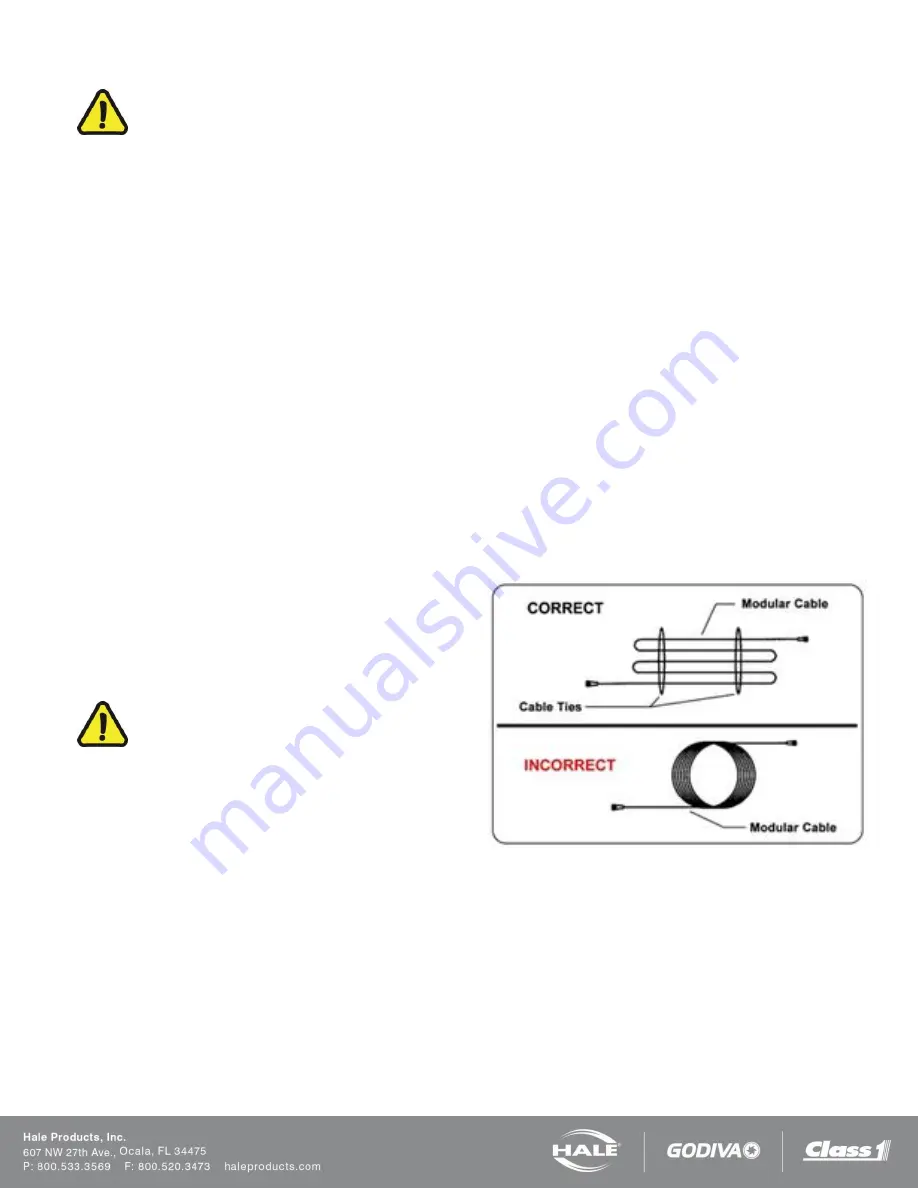
Making round coils of extra control and flow sensor
cables in the pump compartment can act as an antenna.
While the control and flow sensor cables cannot be
shortened, various lengths of cable are available to
minimize the
“extra” cable in the truck.
When routing control and flow sensor cables take care to
avoid routing them next to antenna wires, radio power
lines and radio components. When there is extra cable,
double the cable back on itself and secure with plastic
wire ties in a flat bundle instead of making a round coil.
(See Figure 38
Figure 38
: Extra Cable Storage
Summary of Contents for SmartFOAM 1.7AHP
Page 3: ...Page 2 SmartFOAM NOTES...
Page 14: ...Page 13 SmartFOAM Figure 2 3 3 and 5 0 Foam Pump Installation Envelope Dimensions...
Page 15: ...Page 14 SmartFOAM SYSTEM DIAGRAM Figure 3 Typical Hale SmartFOAM 2 1A and 1 7AHP System...
Page 16: ...Page 15 SmartFOAM Figure 4 SmartFOAM 3 3 5 0 6 5 Single Tank System with In line Strainer...
Page 17: ...Page 16 SmartFOAM Figure 5 SmartFOAM 3 3 5 0 6 5 Single Tank withMSTandIn lineStrainer...
Page 18: ...Page 17 SmartFOAM Figure 6 SmartFOAM 3 3 5 0 6 5 Single Tank withMSTandFSSeriesStrainer...
Page 19: ...Page 18 SmartFOAM Figure 7 SmartFOAM 3 3 5 0 6 5 Dual Tank withMDTIIandIn lineStrainer...
Page 20: ...Page 19 SmartFOAM Figure 8 SmartFOAM 3 3 5 0 6 5 Dual Tank withMDTIIandFSSeriesStrainer...
Page 21: ...Page 20 SmartFOAM Figure 9 SmartFOAM 3 3 5 0 6 5 Dual Tank with ADTandIn lineStrainer...
Page 22: ...Page 21 SmartFOAM Figure 10 SmartFOAM 3 3 5 0 6 5 Dual Tank with ADTandFSSeriesStrainer...
Page 40: ...Page 39 SmartFOAM Figure 18 Typical 4 Inch Check Valve Installation Midship Pump...
Page 51: ...Page 50 SmartFOAM Figure 33 ADT Option Air Hose Connections Part 2...
Page 68: ...Page 67 SmartFOAM NOTES...
Page 80: ...79 Page 79 SmartFOAM NOTES...


