Page
51
SmartFOAM
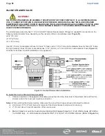
IN-LINE STRAINER VALVE
CAUTION!
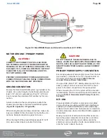
THE IN-LINE STRAINER/VALVE ASSEMBLY, MOUNTED ON THE FOAM PUMP INLET, IS A LOW PRESSURE DE-
VICE. IT CANNOT WITHSTAND FLUSHING WATER PRESSURE. WHEN INSTALLING THE IN-LINE STRAINER
EQUIPPED WITH HALE MDT II OR MST, MAKE SURE THE IN-LINE STRAINER/VALVE ASSEMBLY IS IN THE HOSE
ON THE INLET SIDE OF THE VALVE. IF THE STRAINER IS SUBJECT TO FLUSHING WATER PRESSURE, USE
HALE FS SERIES STRAINERS.
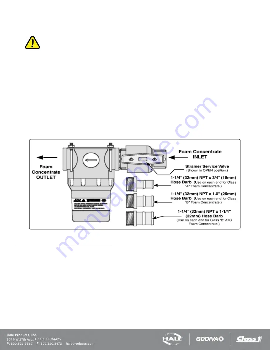
The strainer/valve assembly has 1-1/4” (32 mm) NPT female threaded ports. Fittings are supplied for connection to the
following inside diameter hose, depending on the viscosity of foam concentrates used (
).
❑
3/4” (19 mm)
❑
1.00” (25 mm)
❑
1-1/4” (32 mm)
Use 3/4” (19 mm) inside diameter hose for Class “A” foam and a 1.00” (25 mm) inside diameter hose for Class “B” foams.
For high viscosity Class “B” foam concentrates use 1-1/4” (32 mm) or 1-1/2-in (38 mm) inside diameter hose (
).
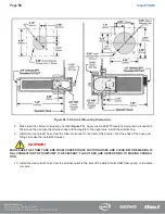
A bracket is included to permit installation on the apparatus.
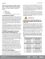
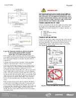
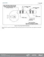
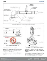
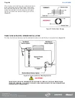
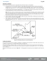
Figure 33: In-Line Strainer/Valve Installation
To Install the In-Line Strainer/Valve Assembly
1. Choose a location on the apparatus that allows gravity feed from the foam tank to the strainer inlet
and
from the
strainer outlet to the foam pump suction connection.
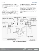
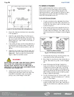
Notes: When selecting the strainer location, make sure there is sufficient space above and below the strainer.
❑
A minimum of 5” (127 mm) below for removal of the strainer basket and screen for cleaning
❑
2” (51 mm) above to permit operation of the service valve
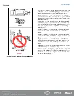
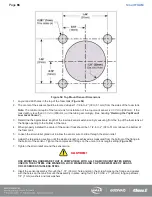
2.
Mark 4 holes to mount the foam strainer bracket. Drill tapped holes for 1/4”-20 UNC screws (#7 drill for
¼-20 UNC tap)...or...drill clearance holes for 9/32” (7 mm) for 1/4”-20 UNC screws. (Refer to
.)
Summary of Contents for MiniCAFS 2.1A
Page 3: ...Page 2 SmartFOAM NOTES...
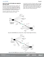
Page 16: ...Page 15 SmartFOAM SYSTEM DIAGRAM Figure 6 Typical Hale SmartFOAM 2 1A and 1 7AHP System...
Page 17: ...Page 16 SmartFOAM Figure 7 SmartFOAM 3 3 5 0 6 5 Single Tank System with In line Strainer...
Page 18: ...Page 17 SmartFOAM Figure 8 SmartFOAM 3 3 5 0 6 5 Single Tank withMSTandIn lineStrainer...
Page 19: ...Page 18 SmartFOAM Figure 9 SmartFOAM 3 3 5 0 6 5 Single Tank withMSTandFSSeriesStrainer...
Page 20: ...Page 19 SmartFOAM Figure 10 SmartFOAM 3 3 5 0 6 5 Dual Tank withMDTIIandIn lineStrainers...
Page 21: ...Page 20 SmartFOAM Figure 11 SmartFOAM 3 3 5 0 6 5 Dual Tank withMDTIIandFSSeriesStrainer...
Page 22: ...Page 21 SmartFOAM Figure 12 SmartFOAM 3 3 5 0 6 5 Dual Tank withADTandIn lineStrainers...
Page 23: ...Page 22 SmartFOAM Figure 13 SmartFOAM 3 3 5 0 6 5 Dual Tank withADTandFSSeries Strainers...
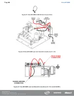
Page 48: ...Page 47 SmartFOAM Figure 28 Typical 4 Inch Check Valve Installation Midship Pump...
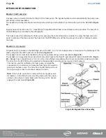
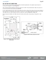
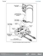
Page 59: ...Page 58 SmartFOAM Figure 43 ADT Option Air Hose Connections Part 2...
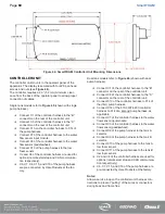
Page 68: ...Page 67 SmartFOAM Figure 55 Top Mount Low Level Sensor Assembly...
Page 77: ...Page 76 SmartFOAM NOTES...
Page 90: ...89 Page 89 SmartFOAM NOTES...


