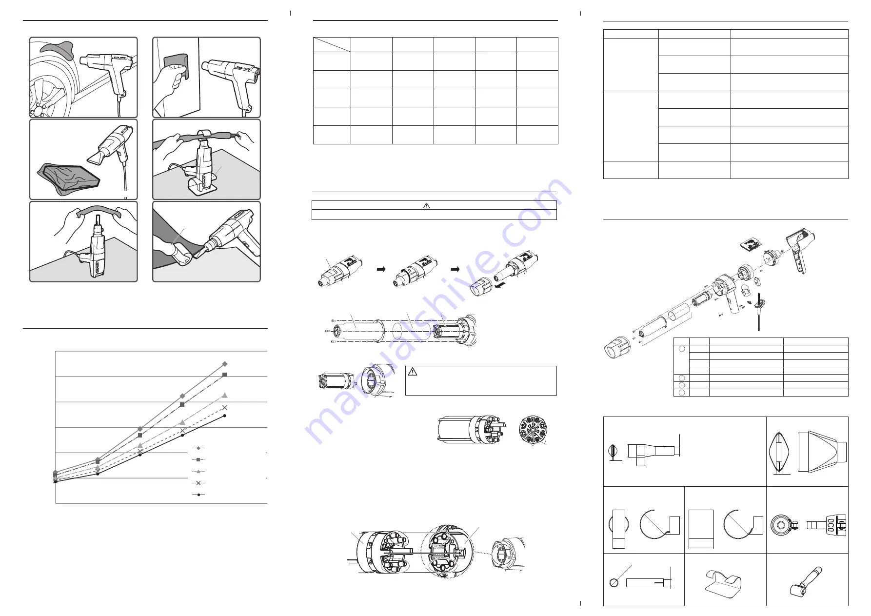
5. TEMPERATURE DISTRIBUTION CHART
5. TEMPERATURE DISTRIBUTION CHART
4. OPERATION
・
Examples of use (Including optional parts*)
7. TROUBLE SHOOTING GUIDE
Problem
No air comes out
The temperature does not
increase (or decrease).
Air flow volume cannot
be adjusted.
Problem Cause
Unit is not connected properly
to power outlet.
Heating element burnout.
Motor is broken.
Unit is not connected properly
to power outlet.
Heating element burnout.
The slide button (switch) is set
to "I".
Temperature control knob or PWB
is broken.
Air flow control knob or PWB is
broken.
Procedure
Connect properly.
In case the resistance value for heater terminal (b) shows
an abnormal value, please replace the heating element.
If no air comes out even if there is no abnormality for the
heating element, that means that the motor is out of order.
Please replace the motor.
Connect properly.
In case the resistance value for heater terminal shows
an abnormal value, please replace the heating element.
Turn the slide button (switch) to "II".
Please contact the distributor or the agency.
Please contact the distributor or the agency.
8. PARTS LIST
Specifications
Part Name
Heating element / 110V
Heating element / 220V
Heating element / 230V
Heating element / 240V
Fan unit / with motor
Pipe cover
Pipe / with mica
Part No.
A5040
A5041
A5043
A5042
B5154
B5162
B5163
Item No.
1
2
3
4
①
②
③
④
※If a problem other than those listed above occurs or if the problem continues even after
performing the solution, contact the distributor or the agency from which you purchased
the unit.
スタンド
The temperature and air flow volume are reference values; these values will not be guaranteed.
* Please refer to “8. PARTS LIST”.
Measured at the point 10mm from the pipe. (without nozzle*)
* When the nozzle is attached, the temperature and air flow volume will change.
Please make sure to adjust both of them when using the unit with a nozzle.
Drying painting and putty
Heat shrink tubing
Use of hook type
nozzle and stand
Peeling sticker
Shrinking
Use of spatula type nozzle
Welding PVC sheet
Use of nozzle holder
and spatula type nozzle
along with roller
Curving plastic
material
Use of
nozzle holder and
single nozzle without stand
Stand
Roller
1
120℃
A,B
110℃
A,B
100℃
A,B
90℃
A
85℃
A
2
175℃
A,B,C
165℃
A,B,C
145℃
A,B,C
130℃
A,B,C
115℃
A,B,C
3
295℃
C,D,E
270℃
C,D,E
230℃
C,D,E
205℃
B,C,D,E
190℃
B,C,D,E
4
425℃
D,E
390℃
D,E
320℃
D,E
285℃
C,D,E
270℃
C,D,E
5
530℃
505℃
425℃
380℃
D,E
345℃
D,E
1
(0.15 m
3
/min)
2
(0.17 m
3
/min)
3
(0.2 m
3
/min)
4
(0.23 m
3
/min)
5
(0.25 m
3
/min)
Examples of use) A: Drying painting and putty B: Peeling sticker C: Shrinking D: Heat shrink tubing
E:
Curving plastic material
0
100
200
300
400
500
600
1
2
3
4
5
Temperature control knob
Temp. (℃)
Air flow control knob
1
Air flow control knob 2
Air flow control knob
3
Air flow control knob
4
Air flow control knob
5
Temp.
Air flow
6. MAINTENANCE / INSPECTION
CAUTION
Replacing the heater can be dangerous. When doing so, be sure to unplug the unit and follow the steps below.
A. Removing the heating element
1. Remove the pipe cover by rotating it anti-clockwise for approx. 20 degrees from
the position when seen from the front
2. Remove the four screws securing the pipe, and remove the pipe and the mica.
3. Pull the heating element straight out.
B. Measuring the resistance
of the heating element
Measure the resistance of the terminals
(a) or (b).
(a) The normal value is 13 Ω (±10% 110V), 56 Ω (±10% 220V), 62 Ω (±10% 230V),
70 Ω (±10% 240V). If the resistance is abnormal, replace the heating element.
(b) The normal value is 115 Ω (± 10% 110V), 300 Ω (±10% 220 - 240V).
If the resistance is abnormal, replace the heating element.
Pipe cover
Pipe
Heating element
Mica
(a)
(b)
C. Attaching the heating element
Please attach the heating element by following the procedure reverse to that for when
removing the heating element.
※Please make sure to attach the heating element by aligning the terminals and the holes
in the fan case.
Fan case
Heating
element
Terminals
After use, the pipe and heating element are
very hot. Please allow them to cool down.
CAUTION
Approx. 20
degrees rotation
●
Optional parts
B5166 Stand
A1115 Roller
N70-02
Spatula type
9
62
(Inside
dimension)
N70-01*
Spatula type
2
13
20
(Inside
dimension)
ø12
(Inside diameter)
ø12
(Inside diameter)
ø12
(Inside diameter)
N70-03 Hook type
N70-04 Hook type
N70-05 Nozzle holder
ø12
ø45
20
ø45
40
N70-06 Single
* W
hen the unit is used
under the condition
below, ALWAYS cool
down after use. Failure
to follow this procedure
may result in blown fuse.
Temperature control knob: level 5
Air flow control knob: level 2 or lower
After use, always turn the slide button (switch) to "I" and allow the unit to cool
down for at least 90 seconds.


