30
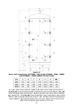
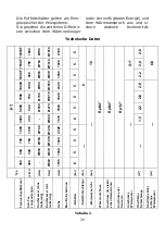
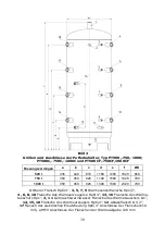
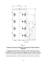
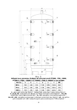
Bild 2
Größen
und Anschlüsse der Pufferbehälter, Typ PT500,
-750,-1000;
PT500C,-750C,-1000C und PT500CF,-750CF,1000CF
Fassungs
vermögen
a
b
c
d
e
f
ØD
500 l
335
440
810
1180
1450
1820
650
750 l
350
450
820
1190
1560
1920
790
1000 l
350
450
920
1390
1860
2320
790
1
Oberer Flansch
Rp6/4”,
3, 5, 7, 9
Wärmesensorflansche Rp1/2”,
4 , 6, 8, 10
Flansche des Wärmeerzeugerse Rp6/4”,
13, 16
Flansche des Wärm
e-
tauschers Rp1”,
2, 11
Gebrauchswarmwasser Flansche des Wärmetauschers G1”,
14, 15, 18
Flan
sche des Wärmeerzeugers Rp6/4”,
12
Ablassflansch G1/2”,
17
Flansch der elektrischen Ersatzheizung Rp6/4”
Anschlüsse der Fla
nschen110
mm, a HMV Anschlüsse der Flanschen der Wärm
eabgabe 120 mm
Summary of Contents for PT 1000 ErP
Page 9: ...9 Aj nlott f t si kapcsol s 1 3 bra...
Page 10: ...10 Aj nlott f t si kapcsol s 2 4 bra...
Page 20: ...20 Recommended heating connection 1 Figure 3...
Page 21: ...21 Recommended heating connection 2 Figure 4...
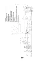
Page 32: ...32 Empfohlene Heizschaltung 1 Bild 3...
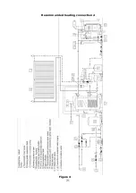
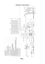
Page 33: ...33 Empfohlene Heizschaltung 2 Bild 4...
Page 39: ...39 110 500 80 PT_CF 300 500 750 1000 PT PT_C PT_CF 9 6 4 1 2 _ PT_CF...
Page 43: ...43 110 120 50 6 4 70 1...
Page 44: ...44 1 3...
Page 45: ...45 2 4...
Page 46: ...46 95o C 7 0 7 PT300 PT300C PT300 PT300C...
Page 47: ...47 1 2 3 4 5 6 7 8 9 10...
Page 48: ...48 60...
Page 49: ...49...
Page 55: ...55 Schem de montaj recomandat 1 Imaginea nr 3...
Page 56: ...56 Schem de montaj recomandat 2 Imaginea nr 4...
Page 70: ...70...
Page 71: ...71...
Page 72: ...72...

