MB6 (6-Slot) Chassis
MB6 Installation
MB6 and MB21 Multichannel Chassis Installation Guide, v2.0, Issue 01
10
To power up the F-MB6X-RAC or F-MB6X-MED Chassis:
1.
Make sure the power switch(es) on the back of the chassis are in the OFF (2) position.
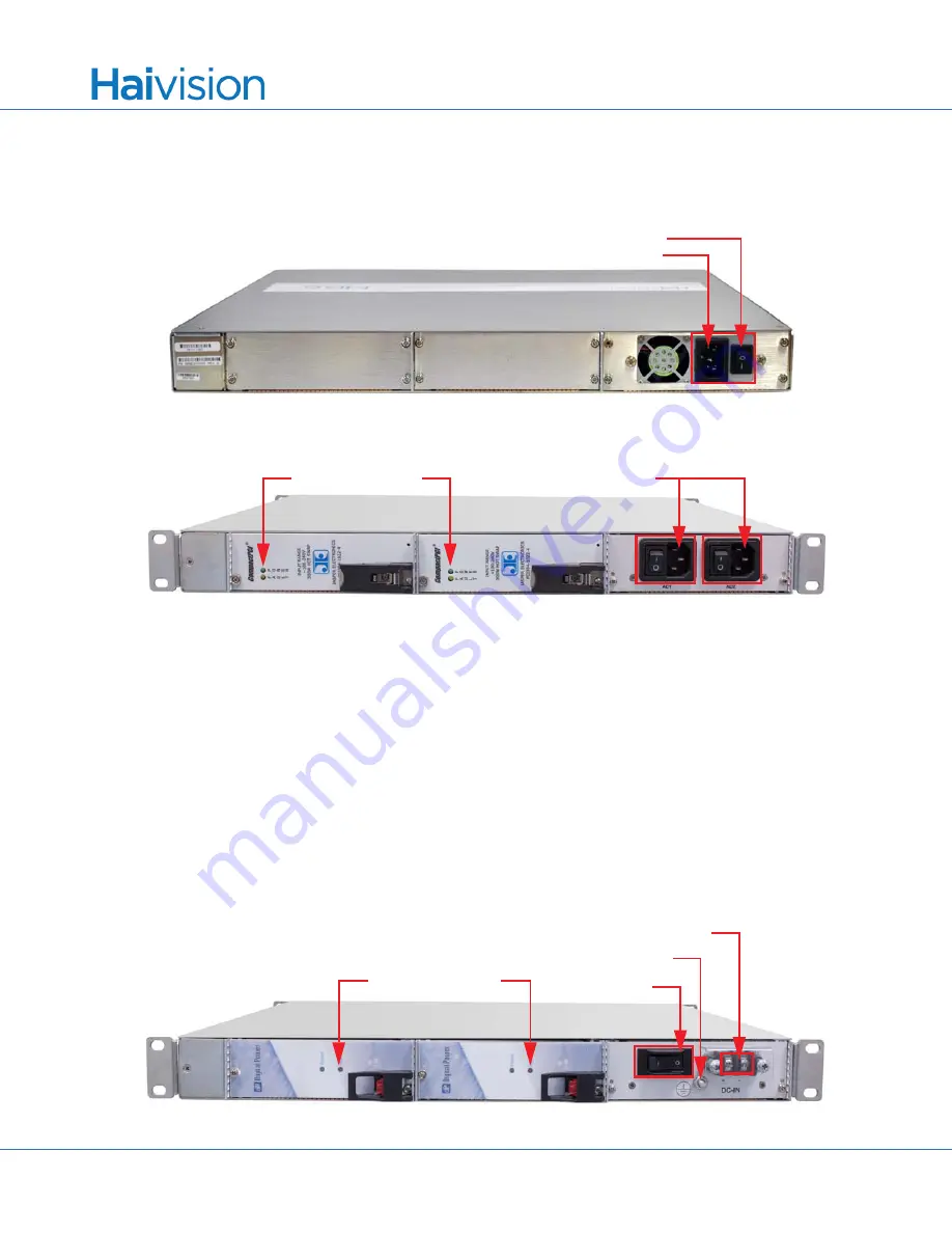
Figure 2: F-MB6X-MED Chassis Rear View showing Power Connector
Figure 3: F-MB6X-RAC Chassis Rear View showing Power Connectors
2.
Connect the power cord(s) to one (or both) of the power receptacles shown in Figures
3.
Plug the cord(s) into a grounded AC power source.
4.
Turn one (or both) PSU Power On/Off switches to the ON (1) position.
On the MB6-RAC, the PSU Status LEDs will turn green indicating that the chassis is powered up.
In the front of either chassis, the Status LEDs will start blinking green, indicating that the encoders/decod-
ers/gateways are booting up.
5.
Wait until the Status LEDs stay solid green, indicating that the chassis is ready for operation.
To power up the F-MB6X-DC-DC Chassis:
1.
Make sure the power switch is in the OFF (2) position.
Figure 4: F-MB6X-DC-DC Chassis Rear View showing Power Connectors
PSU Power On/Off Switch
AC Power Receptacle
PSU Power On/Off Switches
AC Power Receptacles
PSU Status LEDs (green)
PSU Fault LEDs (red)
PSU Power
Positive and Negative Connectors
Ground Lug
On/Off Switch
PSU Status LEDs (green)
PSU Fault LEDs (red)


