Haier NS-F20C, Service Manual
The Insignia NS-F20C's user manual is available for free download on our website. This comprehensive manual provides step-by-step instructions and essential information on utilizing all the features of this outstanding product. Enhance your experience with the Insignia NS-F20C by accessing its user manual on manualshive.com.
Share
Download


Reviews:
No comments
Related manuals for NS-F20C
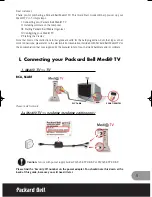
Medi TV
Brand: Packard Bell Pages: 48

43QN9 C Series
Brand: Samsung Pages: 258

CT27E33 - 27" TV
Brand: Panasonic Pages: 81

Adagio ATC-AMFM2
Brand: Crestron Pages: 20

UE49KU6519
Brand: Samsung Pages: 60

WinTV-HVR-1250
Brand: Hauppauge Pages: 2

22LED1500
Brand: Salora Pages: 54

ACTF-DVD1770
Brand: Akura Pages: 14

32HBD274B-N
Brand: Finlux Pages: 17

SRT2113
Brand: Sylvania Pages: 8

NXG-5550
Brand: Skyvue Pages: 52

CT 29BV1 BD
Brand: Mitsubishi Pages: 7

MTK8222
Brand: Hisense Pages: 75

323V
Brand: Olevia Pages: 65

ATV32HDS-1119
Brand: Bauhn Pages: 2

RLED5592A
Brand: RCA Pages: 22

820935
Brand: Ultima Pages: 2

FD171CV VER HD
Brand: Flight Display Systems Pages: 23


