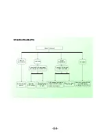
Check if the pin No.1 of CNA1 is 5VSB
Y
N
1. Power Supply Trouble
Change the power board
Y
N
Check if the pin No.2 of UP2
is 3.3VSB
Check if the pin No.7 and No.8 of CNA1
is 5V, and if No.10 is 12V
Y
N
Check the
circuit of
UP2
Y
N
Check if the 1.2V
control circuit of
UP8 is 1.2V
Check if the voltage
on No.2 of CNA1 is
high level
Y
N
UP2
Check the power
control circuit of
QP1
Check if the pin No.3 of
UP8 is PWM signal
Check the voltage
of UP4/3/3V,UD4/1.5V
Y
N
N
QP1
Check if L5/47 H is
welded of damaged.
Y
N
UP8(RT8250)
is damaged
Change
damaged
O
The power
modules is
N
Y
Change
UP8(RT8250)
Change
UP8
Change or
weld L5.
Y
N
circuit LDO
OK
OK
OK
trouble-shooting
-78-
Summary of Contents for MT5311
Page 1: ...MT5311 Training Documents ...
Page 4: ......
Page 5: ......
Page 6: ......
Page 7: ......
Page 8: ...1366 768 16 7M ATSC NTSC 10 75 m mts AC 3 ...
Page 9: ......
Page 10: ...T MT5311 81B CNA2 CN5 CN22 CN18 CON1 CON2 ...
Page 11: ...T MT5311 81B T MT5311 81B 3 4 MINI AV IN SPDIF OUT LINE OUT 1 2 1 ETHERENT ...
Page 12: ...CNA2 CN5 CN18 ...
Page 13: ...CON1 NC Logic Level Control Default For High Level No Connection I2C SCL I2C SDA CN22 ...
Page 15: ......
Page 16: ......
Page 17: ...TC315B601 ...
Page 20: ......
Page 21: ...9 ...
Page 22: ...6 ...
Page 23: ......
Page 24: ......
Page 25: ......
Page 65: ... 64 ...
Page 78: ... 77 ...
Page 88: ... 87 ...
Page 89: ... 88 ...
Page 90: ... 89 ...
Page 91: ... 90 ...


