Haier L52A18-A, User Manual
Looking for a hassle-free way to access the user manual for the Haier L52A18-A? Look no further! With just a few clicks, you can download the manual for free from manualshive.com, ensuring that you have all the necessary information to make the most out of your Haier L52A18-A experience.
Share
Download


Reviews:
No comments
Related manuals for L52A18-A

E420-AO
Brand: Vizio Pages: 46

UE55D6000TK
Brand: Samsung Pages: 24
LOG32LW782
Brand: Logik Pages: 47

OLE 32150-B
Brand: OK. Pages: 140

PS1980
Brand: Magnavox Pages: 32
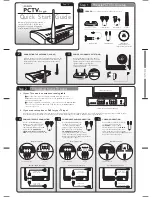
PCTV To Go
Brand: Pinnacle Pages: 2

GETAC V110 CRADLE
Brand: Gamber Johnson Pages: 3

SP-2110012
Brand: Speaka Professional Pages: 4

NS-32LCD
Brand: Insignia Pages: 78

43P610
Brand: TCL Pages: 16

82V42UHD
Brand: Vidao Pages: 40

SLED2280A
Brand: Sansui Pages: 27

FCM-0700A
Brand: Polaroid Pages: 24

DTA-1420
Brand: Daewoo Pages: 31

YUL201
Brand: AVF Pages: 12

i3SWEEZZ
Brand: i3-TECHNOLOGIES Pages: 5

43-FFD-4220
Brand: Finlux Pages: 44

UE ES55 Series
Brand: Samsung Pages: 169


