25
6. DISASSEMBLY INSTRUCTIONS
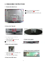
1. Remove the Back Cover
①
Remove the twelve screws indicated
on figure above by
②
Then remove the back cover from the unit.
2. Remove the Pedestal
①
Lay down the unit so that rear
cover faces upward
②
Remove the four screw from the rear
cover indicated with
③
Then remove the pedestal.
3.Remove the power module
①
Remove the four screws indicated on the
figure above by
②
Then remove the power module
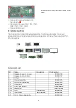
4. Remove the Main board
5
.
Remove the speaker
Remove the four screws, take out the speaker
6
.
Remove the remote control board
Summary of Contents for L40R1
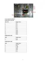
Page 8: ...8 3 2 2 Connector definition Power connector CNA1 MTk5380 ...
Page 21: ...21 Power source Removing the table stand and installing a wall mount bracket ...
Page 31: ...31 4 Channel 5 Gamma 6 BackLight ...
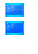
Page 32: ...32 7 Function ...
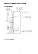
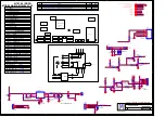
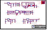
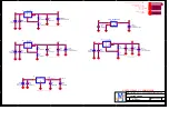
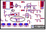
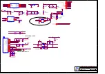
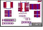
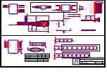
Page 33: ...33 8 BLOCK DIAGRAM AND CIRCUIT DIAGRAM 8 1 BLOCK DIAGRAM 8 2 CIRCUIT DIAGRAM MTK5380 ...
Page 49: ...0090403331 ...
Page 50: ...50 10 TROUBLE SHOOTING GUIDE 10 1 Simple check 10 1 1 LCD is not bright 10 1 2 No picture ...
Page 55: ...55 ...

