appropriately. To get the best picture quality,
adjust the output resolution of the source device, if
available, to 1280
s
720 for the 32" TV and 1920 x 1080
for the 37" and 42" TVs.
Press the INPUT button to select the corresponding
•
HDMI input source.
When the source device (DVD player , Bluray player, or
Set Top Box) supports DVI.
How To Connect
Connect the source device to the HDMI port of the
A
TV with a HDMI-to-DVI cable (not supplied with this
product).
A separated audio connection is necessary.
B
If the source device has an analog audio output
C
connector, connect the source device audio output to DVI
Audio In port located on the left side of the HDMI port.
How To Use
If the source device supports the Auto DVI
•
function, the output resolution of the source
device will be automatically set to the appropriate
resolution1280
s
720p for the 32" TV and 1920 x 1080
for the 37" and 42" TVs.
If the source device does not support the Auto DVI,
•
you need to set the output resolution appropriately.
To get the best picture quality, adjust the output
resolution of the source device , if available, to
1280
s
720p for the 32" TV and 1920 x 1080 for the 37"
and 42" TVs.
Press the
•
INPUT
button to select the corresponding
HDMI input source.
Connecting Headphones
You can connect a set of headphones to your set if you
wish to watch a TV program without disturbing the
other people in the room.
28
';*/55;:
Plug a set of headphones into the 3.5mm mini-jack socket
on the side panel of the set.
Note
Prolonged use of headphones at a high volume may
R
damage your hearing.
You will not receive sound from the speakers when
R
you connect headphones to the system.
Power source
TO USE AC POWER SOURCE
Use the polarized AC line cord provided for operation
•
with AC power. Insert the AC cord plug into a standard
polarized AC outlet.
Note
Never connect the AC line cord plug to other than
R
the specified voltage. Use the attached power cord
only.
If the polarized AC cord does not fit into a non-
R
polarized AC outlet, do not attempt to file or cut
the blade. It is the user’s responsibility to have an
electrician replace the obsolete outlet.
If you cause a static discharge when touching the
R
unit and the unit fails to function, simply unplug the
unit from the AC outlet and plug it back in. The unit
should return to normal operation.
Polarized AC Cord Plug
AC Outlet
Wider Hole
and Blade
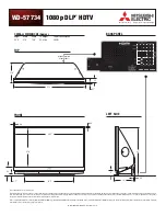
Service Manual
Model No.: HL37XLE2
23
Summary of Contents for HL37XLE2
Page 10: ...Service Manual Model No HL37XLE2 9 2 2 External pictures four faces Front Side Left Side ...
Page 11: ...Service Manual Model No HL37XLE2 10 Right Side Back Side ...
Page 49: ...8 2 4 Picture Mode Service Manual Model No HL37XLE2 48 ...
Page 50: ...8 2 5 Audio Mode Service Manual Model No HL37XLE2 49 ...