


Page 21
31-5000736 Rev. 0
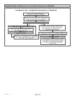
Typical Operating Characteristics
Blower Operation and Adjustment
NOTE:
The following is a generalized procedure and does
not apply to all thermostat controls.
1.
Blower operation is dependent on thermostat control
system.
2.
Generally, blower operation is set at thermostat
subbase fan switch. With fan switch in ON position,
blower operates continuously. With fan switch in
AUTO position, blower cycles with demand or runs
continuously while heating or cooling circuit cycles.
3.
Depending on the type of indoor thermostat, blower
and entire unit will be off when the system switch is in
OFF position.
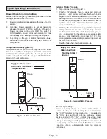
Temperature Rise (Figure 17)
Temperature rise for NF80DS units depends on unit input,
blower speed, blower horsepower and static pressure as
marked on the unit rating plate. The blower speed must be
set for unit operation within the range of “TEMP. RISE °F”
listed on the unit rating plate.
Figure 17. Temperature Rise
Return
Supply
Temperatures
Supply Duct Temperature
Return Duct Temperature
_
Temperature Rise =
External Static Pressure
1.
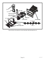
Tap locations shown in Figure 18.
2.
Punch a 1/4” diameter hole in supply and return air
plenums. Insert manometer hose flush with inside
edge of hole or insulation. Seal around the hose with
permagum. Connect the zero end of the manometer to
the discharge (supply) side of the system. On ducted
systems, connect the other end of manometer to the
return duct as above.
3.
With only the blower motor running and the evaporator
coil dry, observe the manometer reading. Adjust blower
motor speed to deliver the air desired according to the
job requirements. For heating speed external static
pressure drop must not be more than 0.5” W.C. For
cooling speed external static pressure drop must not
be more than 0.8” W.C.
4. Seal the hole when the check is complete.
Figure 18. External Static Pressure
Supply Duct Static
Return Duct
Total Duct Static =
(dry coil)
Return
Supply
Blower Speed Taps
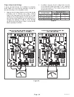
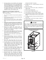
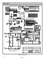
Blower speed tap changes are made on the integrated
control. See Figure 3. The heating tap is connected to
the “HEAT” terminal and the cooling tap is connected to
the “COOL” terminal. On all units the continuous blower
tap is connected to the “FAN” terminal. Unused taps must
be secured on two dummy terminals labeled ”PARK. To
change out existing speed tap, turn off power and switch
out speed tap with tap connected to “PARK”. See blower
speed tap table on unit diagram for motor tap colors for
each speed.