background image

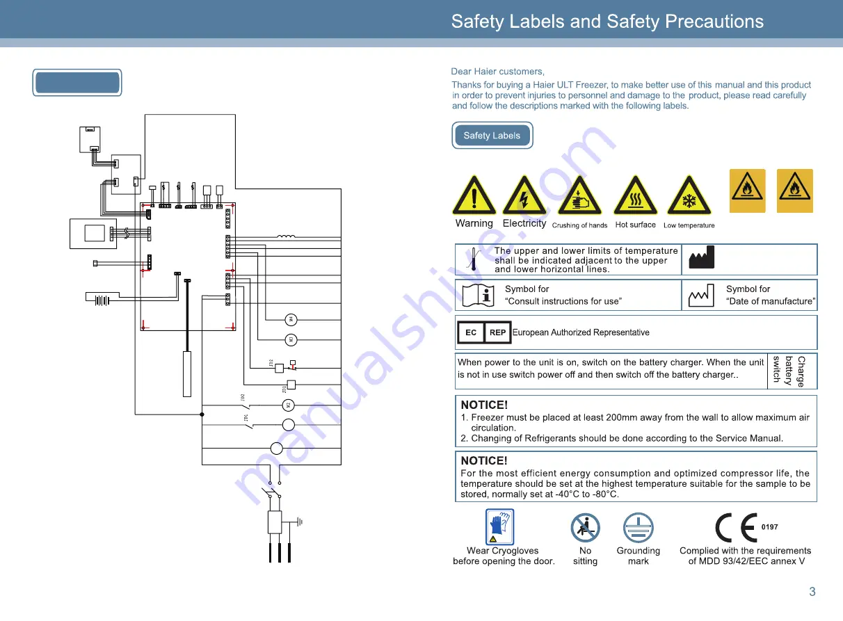
Thermograph

M

5

Li

ne

 B

la

nk

 fo

r R

em

ot

Al

ar

m

Chargebl

B

at

te

ry

Te

m

pera

tu

re

 S

en

so

In

si

de

 C

ab

in

et

Pressure Switch

2nd stage compressor

Di

spal

bo

ar

d

Control  Panel

M

1

L

N

1st stage compressor

Condensor

 Sensor

Li

ne

 B

an

fo

r B

ac

ku

Sy

st

em

Pr

ox

im

ity

 S

w

itc

fo

r Doo

r O

pen

ing

P

ower

 S

upp

ly


Ha

m

es

fo

W

irel

es

Ne

twork


S

ys

tem

Ba

la

nc

ed

 h

ea

tin

st

rip

Absorption Fan

Heating module for capillary tube

U

S

B

co

nn

ec

to

bo

ar

U

S

B

 Dri

ver


B

oa

rd

PE

Fi

lte

r

P

ow

er

S

wi

tc

h

Absorption Fan

Te

m

pe

ra

tu

re

 S

en

so

r f

or


H

ea

t E

xc

ha

ng

er

Wiring Diagram

30

Wear Cryogloves

Haier Biomedical UK

Email: [email protected]

Symbol for

“Manufacture”

TEL: +44(0) 1825 744 696

R170

R290

R170

R290

Summary of Contents for DW-86L338J

Page 1: ...DW 86L578J DW 86L728J Version 1st 2016 Dedicated code 0270500680A Web www haiermedical com Translation of the original instruction Manufacturer code V13026 DW 86L338J DW 86L388J DW 86L490J DW 86L828J ...

Page 2: ......

Page 3: ...us malfunction alarms high temperature alarm power failure alarm probe failure alarm hot condensor lalarm high ambient temperature alarm doors open alarm low battery alarm Mulyiple protections function password protection power up delay protection DW 86L338J 338 50 238 812 893 1846 220 240 7 5A 1 1 1 1 4 4 8 4 4 4 2 DW 86L338J DW 86L388J 388 50 255 812 893 1980 220 240 8A 1 1 1 1 2 DW 86L388J DW 8...

Page 4: ... 26 28 29 31 Foaming Cabinet CP IP DW 86L338J DW 86L388J DW 86L490J 31 USB Standard 2 Stainless shelves height adjustable Setting the USB storage time 18 Exporting USB data 19 R290 R170 Door open alarm DW 86L578J DW 86L728J DW 86L828J ...

Page 5: ... System Proximity Switch for Door Opening Power Supply Hamess for Wireless Network System Balanced heating strip Absorption Fan Heating module for capillary tube USB connector board USB Driver Board PE Filter Power Switch Absorption Fan Temperature Sensor for Heat Exchanger Wiring Diagram 30 Wear Cryogloves Haier Biomedical UK Email uksales haierbiomedical com Symbol for Manufacture TEL 44 0 1825 ...

Page 6: ...nduct by technicians approved by manufacturer High Stage Compressor Low Stage Compressor Oil Separator Filter Dryer Pressure Switch Cascade Condenser Capillary Tube Capillary Tube Filter Dryer Precondenser Evaporator Suction Accumlator Condenser anti condensation ...

Page 7: ...28 The wastes of the freezer need to be disposed by specialized personnel no arbitrary movement of it is allowed or otherwise events of kids being shut in it may occur ...

Page 8: ...ay and understand the hazards involved Children shall not play with the appliance Cleaning and user maintenance shall not be made by children without supervision If the supply cord is damaged it must be replaced by the manufacturer its service agent or similarly qualified persons in order to avoid a hazard Users must not dismantle repair or modify the equipment Such improper operations may result ...

Page 9: ...26 If the free standing back up system is to be connected to DW 86L490J it s necessary to buy the relative switch box and plate ...

Page 10: ...r the power outage alarm It is located inside the control corner of the right side of the unit Two ancess port is installed in the back wall of the unit which can be used as the REMOTE ALARM MAX DC30V 2A Battery Switch POWER on off on off SWITCH ...

Page 11: ...r information regarding the collectionsystems available If electrical appliances are disposed of in landfills or dumps hazardoussubstances can leak into the groundwater and get into the food chain damaging yourhealth and well being When replacing old appliances with new ones the retailer is legallyobligated to take back your old appliance for disposals at least free of charge ...

Page 12: ...23 4000W ...

Page 13: ...22 REMOTE ALARM MAX DC30V 2A Battery Switch POWER on off on off SWITCH box on the right side of the unit The alarm signals are delivered via the terminals The terminals are rated for 30V DC at 2A ...

Page 14: ...12 21 REMOTE ALARM MAX DC30V 2A Battery Switch POWER on off on off SWITCH ...

Page 15: ...13 20 inner ambient ...

Page 16: ...rs press Set key to change the setting If no adjustments need to be made press key the display shows Minutes 5P and you can make changes 6 changes will be saved and the settings will be automatically exited from Then the temperature display will normally show the inner temperature Push for 3 seconds Push for 5 seconds the settings if no other settings do not need to be changed you can just press a...

Page 17: ... the changes Then the temperature display steadily shows 2P Follow the procedure above to set 2P 3P 4P and 5P respectively and press Set key to save the changes Then the temperature display will show 1P again and you can set 1P to 5P again For example Set the time as 08 30 Aug 16 2013 3 After the settings are completed press and hold Set for 5 seconds the changes will be saved and exit the setting...

Page 18: ...16 17 ...

Reviews: