background image

Circuit Diagram and Circuit Explanation 

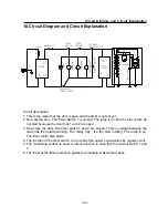
10.Circuit Diagram and Circuit Explanation 


Circuit description: 
1. This is the mode that the door is open and the timer is not set yet. 
2. Now set the time. The Timer Switch 1 is closed. The lamp is on. But the other parts do 

not start because the door lock 1 and 2 are open. 

FILTER

  N

IN

L

IN

N

   E

L

F

U

S

E

TIMER
SWITCH1

TIMER
SWITCH2

THR FRIST 
LOOKOUT SWITCH

MT

FA
NM
OTOR

TI
ME
RMOTOR

M

MF

THR SECOND 
LOCKOUT SWITCH

  N

OUT

  L

OUT

THERMOSTAT

LA
MP

MO
NI
TO
RI
NGSWITCH

CUR

BRIN

GMOT

OR

DELAY 
CIRCUIT

  T

IN)

  SW

HV
-R
EC
TIFIER

  P

OUT)

AK 
RECTIFIER

HVT

HVC

MAG

NETR

ON

3. Now close the door. The timer switch 1 and 2 are closed. There is voltage between the 

two ends then starts working. The rotary tray , the fan start rotating. The lamp is on. 
The timer motor also starts. 

4. The function of the timer switch 2 is to control the power consumption by regular on/off. 
5. The monitoring surface is used to offer protection in case that the lockout switch 1 and 

2. 

6. The thermostat offers protection against overheating in abnormal cases. 


- 24 - 

Summary of Contents for Bauer HR-6752D

Page 1: ...ll Microwave Oven Service Manual TIM E MI CRO W A VE O VEN POW ER HR 6802TA HR 6802TK HR 6752D Features Safe to use Shining appearance Healthy and germicidal Easy to operate Haier Group Manual code EUMWOM 01 Edition 2003 1 8 ...

Page 2: ...tion 2 3 Features 3 4 Specifications 4 5 Safety Precaution 5 6 Warning and Cautions 6 7 Installation and Accessory Parts 9 8 Parts and Functions 11 9 Maintenance Service and Trouble Shooting 12 10 Circuit Diagram and Circuit Explanation 23 11 Exploded View 27 12 List of Parts 30 1 ...

Page 3: ...attern 1 3 means the operation pattern is electronic 2 5 means the operation pattern is mechnical E Function code G with grill F Appearance feature Examples HR 6752D It represents mechnical microwave oven without grill the cavity capacity is 17 liter the microwave output power consumption is 750 Watts HR 6802TA It represents mechnical microwave oven without grill the cavity capacity is 17 liter th...

Page 4: ...e door shell and operation panel frame shell adopt in ported high quality stainless steel material and will never get rust and change color It has modern appearance and superior quality and thus becomes the best choice for the household microwave oven 3 3 Healthy and germicidal It is produced with antiseptic materials and can suppress the reproduction of the bacteria effectively The special functi...

Page 5: ...umption For grill Oscillating frequency 2450MHz Timing range 60 Power level 6 6 Unit Dimension W D H mm 458 337 295 458 342 295 Cavity Dimension W D H mm 302 288 183 302 288 183 Carton Dimension W D H mm 514 374 348 514 394 348 Volume effective volume 17 11L Weight unit carton 13 15Kg Accessories Instruction manual glass tray turn plate bracket groupwaregl turn axis 4 ...

Page 6: ... consumption For grill Oscillating frequency 2450MHz Timing range 60 Power level 6 Unit Dimension W D H mm 458 337 295 Cavity Dimension W D H mm 302 288 183 Carton Dimension W D H mm 420 380 360 Volume effective volume 17 11L Weight unit carton 13 15Kg Accessories Instruction manual glass tray turn plate bracket groupwaregl turn axis 5 ...

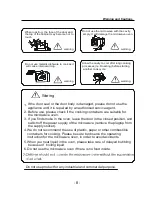
Page 7: ...n the power to do maintenance or check the functional components 4 In case that the door lock seal gasket microwave radiating and transmission system are damaged or something wrong in debugging please make repair replacement or adjustment according to the requirement of this manual before usage Components detachable that may touch voltage higher than 250V Components that may cause excessive microw...

Page 8: ...or and result in microwave leakage warning warning Electric shock hazard Do not use a metal rod to enter the interlock switch hole on the front side of the cavity interlock switch hole No dismantle Danger This appliance must be earthed Remember to clear away excess grease form the inside the cavity Otherwise it may cause smoke or fire during heating Do not use sealed containers For those foods wit...

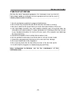
Page 9: ...se be sure to observe the operating instruction for the microwave oven in order to avoid accidents 5 When you heat liquid in the oven please take care of delayed bubbling because of boiling liquid 6 Do not use the microwave oven if there is no food inside 7 Waring warning warning When roasting the face of the door and the top of the cabinet may become hot to touch Do not use the microwave with the...

Page 10: ...tricity even 30 seconds after the microwave oven stops working To make replacement or checking at this time be sure to use insulated screwdriver to short out the two ends of the capacitor and discharge the stored electricity 5 Prevent the wristwatch from touching the microwave oven 6 Do not operate the microwave oven when there is no food or water inside 7 Protect the seal gasket and front board o...

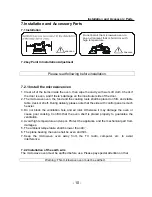
Page 11: ...d on firm and stable table desk or shelf During delivery please note that the side with control panel is much heavier 3 Do not block the ventilation hole and air inlet Otherwise it may damage the oven or cause poor cooking Confirm that the oven shelf is placed properly to guarantee the ventilation 4 Avoid high temperature and vapor Protect the appliance and the mechanical part from damages 5 The a...

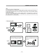
Page 12: ...own wire to the wire marked with L or the red wire 7 3 Accessory parts Open the carton Install Put the microwave oven at the position you choose Keep good ventilation The gaps should all be above 15cm accessory box T IM E WE I GH T AD J US T A UT OCO O K IN GME N U 1 B e v e r ag e 2 F is h 3 A ut o R eh e a t 4 I ns t a n t N oo d l e 5 B ar b e c u e 6 V eg e t a b le 7 C hi c k e n 8 A ut o D e...

Page 13: ...Parts and Functions 8 Parts and Functions glass rotary tray shell operation board diagrammtic sketch for baking mesh cavity door hook door seal door h b d 12 ...

Page 14: ...MF THR SECOND LOCKOUT SWITCH N OUT L OUT THERMOSTAT LAMP MONITORINGSWITCH CURBRINGMOTOR DELAY CIRCUIT T IN SW HV RECTIFIER P OUT AK RECTIFIER HVT HVC MAGNETRON 3 Now close the door The timer switch 1 and 2 are closed There is voltage between the two ends then starts working The rotary tray the fan start rotating The lamp is on The timer motor also starts 4 The function of the timer switch 2 is to ...

Page 15: ...o ends of the heater winding 3 The 2000V voltage will be doubled by the high voltage capacitor then be rectified by the high voltage diode finally become a 4000V negative high voltage to ground at the FA end of the magnetron 4 One end of the heater coil is connected to the negative high voltage the other end to the F end of the magnetron Therefore the working condition of the magnetron is made up ...

Page 16: ...Sincere Forever Haier Group Tel 86 532 8938356 Web site http www haier com ...

Reviews: