


26
System configuration
Domestic air conditioner
Outdoor Unit
Loading of the battery
1
2
3
4
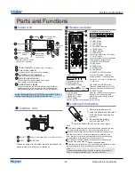
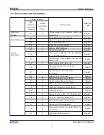
Parts and Functions
Indoor Unit
OUTLET
INLET
CONNECTING PIPING AND ELECTRICAL WIRING
DRAIN HOSE
Remote controller
Remove the battery cover;
Load the batteries as illustrated.
2 R-03 batteries, resetting key
(cylinder);
Be sure that the loading
is in line with th
e" + "/"-";
Load the battery,then put on the cover again.
The distance between the signal transmission head and the rece-
iver hole should be within 7m without any obstacle as well.
When electronic-started type fluorescent lamp or change- over
wireless telephone is installed in the
ver is apt to be disturbed in receiving the signals,
so the distance to the indoor unit should be shorter.
type fluorescent lamp or
room, the recei
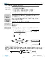
Note:
Full display or unclear display during operation indicates the
ries have been used up. Please change batteries.
If the remote controller can't run normally during operation, please
reload several minutes later.
batte
remove the batteries and
Please be subject to the actual produce purchased the
above picture is just from your reference
4
Hint:
Remove the batteries in case won't be in use for a long period. If
there is any display after taking-out, just press reset key.
Healthy function is not available for some units.
1. Mode display
2. Signal sending display
4. FAN SPEED display
5. LOCK display
6. TIMER OFF display
TIMER ON display
7. TEMP display
16. LOCK button
Used to lock buttons and LCD display
25. RESET button
When the remote controller appears
abnormal, use a sharp pointed
article to press this button to reset
22. HOUR button
Control the lightening and extinguishing
of the indoor LED display board.
8.
9. QUIET button
11. COOL button
10. HEAT button
12. AUTO button
13. FAN SPEED button
14. TIMER button
15. HEALTH button
17. LIGHT button
18. POWER ON/OFF button
19. DRY button
20. TEMP button
21. SWING button
23. EXTRA FUNCTION button
24.CANCEL/CONFIRM button
Function: Setting and cancel to the
timer and other additional functions.
3. SWING display
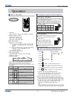
Operation mode
AUTO
FAN
COOL
DRY
Remote controller
HEAT
LO
MED
HI
AUTO
Display
circulated
the remote.
Additional functions display
1
2
3
4
5
9
10
11
12
13
14
15
16
17
8
22
23
24
25
19
20
21
18
7
6
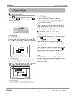
Operation mode
Remote controller
QUIET
TURBO
SLEEP
Supplemented
electrical
heating
HEALTH
Function: Sleeping---- Healthy
airflow position1--- Healthy airflow
position 2 --- Power --- Air sending
--- A-B yard
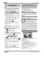
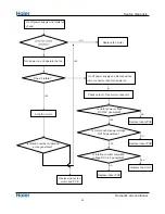
Actual inlet grille may vary from the one shown in the
manual according to the product purchased
(adjust left and
ow)
Vertical blade
r ight air fl
Air Purifying Filter
Inlet
(inside)
Emergency
Switch
Horizontal flap
(adjust up and down air flow
Don't adjust it manually)
Outlet
Inlet grille
6
5
2
1
4
3
6
4
2
1
5
3
(inside)
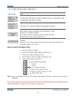
Power indicator
Timer mode indicator
Operation mode indicator
(Lights up when unit starts.)
(Lights up whenTimer operation is selected.)
(lights up when the compressor is on.)
Remote signal receiver
(A beeping sound is generated when a signal
from remote controller isreceived.)
Ambient temp display
When receiving the remote control signal, display the set
temperature and in the rest time the room temperature is
displayed and this room temperature is only for reference.
7
11
10
8
9
Anion generator
12
9
10
11
12
13
13
Summary of Contents for AS12GB3HRA
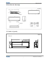
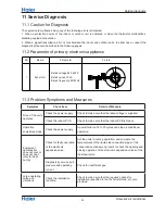
Page 12: ... Piping diagrams Domestic air conditioner 5ˊPinping diagrams 10 ...
Page 58: ... Circuit diagrams Domestic air conditioner ...
Page 60: ...Removal of procedure 1 Removal of Air Filter 1 Domestic Air Condition ...
Page 63: ...Removal of procedure three two HOOKS 4 Domestic Air Condition ...
Page 65: ...Removal of procedure 4 Removal of Drain pan 6 Domestic Air Condition ...
Page 66: ...Removal of procedure 5 Removal of vertical blades and swing motor 7 Domestic Air Condition ...
Page 67: ...Removal of procedure 6 Removal of Electrical Box 8 Domestic Air Condition ...
Page 68: ...Removal of procedure 7 Removal of Heat Exchanger 9 Domestic Air Condition ...
Page 69: ...Removal of procedure 10 Domestic Air Condition ...
Page 70: ...Removal of procedure 8 Removal of Fan Rotor and Motor 11 Domestic Air Condition ...
Page 71: ...Removal of procedure 12 Domestic Air Condition ...


