


AUDIO-R
AUDIO-L
VIDEO
AUDIO-R
AUDIO-L
VIDEO
Antenna
4
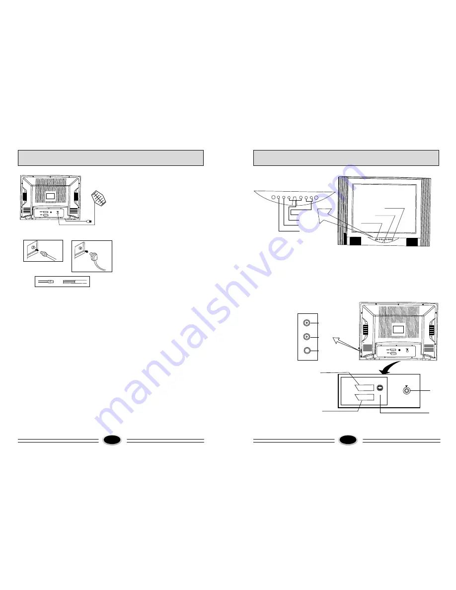
FUNCTION BUTTONS AND EXTERNAL SOCKETS
Figure A
Figure B
Antenna cable
with a plug
Figure C
Figure D
Antenna feeder
Antenna adapter
75-300
Ω
Coaxial cable(75
Ω
) twin-lead cable(300
Ω
)
Antenna Connection
Connect an antenna to the antenna socket on
the TV set,we recommend using a Cable TV
system for better picture and audio quality.
1.If you use a coaxial cable(75
),insert the
antenna plug (see figure C) into 75
socket
(see figure A).
2.If you use a twin-lead cable(300
),please
shape the cable as figure D,and connect the
leads to antenna adapter and then insert the
antenna adapter into the 75
socket.(see
figure B)
Power source wire connection
Insert the power plug into AC outlet.
To install and to replace batteries of the remote
control unit
1.Place the remote control unit with the face
down, then open the battery cover of the unit.
2.Place the two"AA"size batteries, matching
the + and - signs on each battery to the +
and -signs of the battery compartment.
3.Close the cover of the battery compartment.
NOTE:
(1)Don't drop or wet or dismantle the unit.
(2)If you don't intend to use the unit for a
long period or the electricity of the
batteries is used up, remove the batteries
to prevent batteries acid from leaking into
the battery compartment.
(3)Always replace both batteries at the same
time.
(4)Do not use rechargeable batteries (Ni-cd)
or mix battery types.
(5)Never place batteries in a fire. Dispose
of the batteries with your domestic
rubbish collection.
Ω
Ω
Ω
Ω
FUNCTION BUTTONS AND EXTERNAL SOCKETS
3
1.Front panel
(1)S-VHS input
(2)SCART1 socket
(3)SCART2 socket
(4)Antenna input
SCART1
SCART2
S-VHS
(3)
(2)
(4)
(1)
(2)
(3)
(1)
(5)
(6)
(7)
(4)
MENU
V-
V+ P-
P+
TV/AV
(1)Remote sensor: let the remote controller aim here the set can receive remote
control signal.
(2)Power switch: press the button to turn on the TV set . press the button again to turn
off the TV set.
(3)Power indicator: the indicator lights in standby status ,the indicator lights in sleep
status . The indicator glints when you use remote controller.
(4)Menu button
(5)Program up/down button
(6)Volume up/down button
(7)TV/AV
2.Rear Panel


