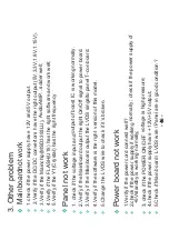
M
a
inbo
a
rdnot
w
or
k
1.chec
k
i
f
the po
w
er supply h
a
ve
1
2V
a
nd 5
V
output.
2
.
V
eri
f
y i
f
the DC/DC convertors
h
a
ve the ri
g
ht output
(5
V
,3.3
V
,1.8
V
,1.15
V
).
3.
V
eri
f
y i
f
the M
a
inchip(M
S
D3393LU),
A
udio
A
MP…solder
w
ell;
4.
V
eri
f
y i
f
the FL
AS
H(U18) h
a
s the
ri
g
ht so
f
t
wa
re
a
nd
w
or
k
w
ell;
5.
V
eri
f
y i
f
the Y1(Cryst
a
l) h
a
s the
ri
g
ht
f
re
q
uency
P
a
nel not
w
or
k
1.
chec
k
i
f
the volt
ag
e input
a
nd
output o
f
boost IC is
w
or
k
in
g
nor
ma
lly.
2
.
V
eri
f
y i
f
the M
a
inbo
a
rd
output the
ri
g
ht On/O
ff
si
g
n
a
l to po
w
er bo
a
rd.
3.
V
eri
f
y i
f
the M
a
inbo
a
rd
output the
L
V
D
S
sin
ga
lto p
a
nel T-con bo
a
rd.
4.
V
eri
f
y i
f
the so
f
t
wa
re is the ri
g
ht
version o
f
this
m
odel.
5.Ch
a
n
g
e the L
V
D
S
w
ire to chec
k
i
f
it’s bro
k
en.
- 46 -
3. Other proble
m
Po
w
er bo
a
rd not
w
or
k
1.
V
eri
f
y i
f
the po
w
er cord connect
w
ell?
2
.chec
k
i
f
the po
w
er supply i
f
w
or
k
in
g
nor
ma
lly ; chec
k
i
f
the po
w
er supply o
f
+5
V
st
a
ndby is
w
or
k
in
g
nor
ma
lly;
3.
chec
k
i
f
the POWER ON/OFF
volt
ag
e is hi
g
h pressure;
4.chec
k
i
f
the po
w
er supply h
a
ve
+1
2V
/+5
V
output;
5.Chec
k
i
f
M
a
in bo
a
rd / L
V
D
S
w
ire /
P
a
nel
a
re in
g
ood condition ?
Summary of Contents for 24D3000
Page 11: ...3 3 LED Panel 10 Service Manual Model No MTC236LED C09H CMO V236BJ1 P01 ...
Page 15: ...4 6 Remove the remote control take out the remote controlboard Service Manual Model No 14 ...
Page 17: ... 16 ...
Page 18: ... 17 ...
Page 19: ... 18 ...
Page 23: ...Service Manual Model No 6 Operation Instructions Basal information 22 ...
Page 24: ...6 3 Setting Up Your Remote Control Service Manual Model No 23 ...
Page 38: ...Service Manual Model No 9 Trouble shooting 9 1 Simple check 38 ...


