4
Value
Character
Value
Character
Value
Character
Value
Character
Dec Hex
Dec Hex
Dec Hex
Dec Hex
00
01
02
03
04
05
06
07
08
09
10
11
12
13
14
15
16
17
18
19
20
21
22
23
24
25
26
27
28
29
30
31
00
01
02
03
04
05
06
07
08
09
0A
0B
0C
0D
0E
0F
10
11
12
13
14
15
16
17
18
19
1A
1B
1C
1D
1E
1F
none
none
none
none
none
none
none
none
Backspace
Tab
none
none
none
Return
none
none
none
none
none
none
none
none
none
none
none
none
none
Esc
none
none
none
none
32
33
34
35
36
37
38
39
40
41
42
43
44
45
46
47
48
49
50
51
52
53
54
55
56
57
58
59
60
61
62
63
20
21
22
23
24
25
26
27
28
29
2A
2B
2C
2D
2E
2F
30
31
32
33
34
35
36
37
38
39
3A
3B
3C
3D
3E
3F
Space
!
“
#
$
%
&
‘
(
)
*
+
,
_
.
/
0
1
2
3
4
5
6
7
8
9
:
;
<
=
>
?
64
65
66
67
68
69
70
71
72
73
74
75
76
77
78
79
80
81
82
83
84
85
86
87
88
89
90
91
92
93
94
95
40
41
42
43
44
45
46
47
48
49
4A
4B
4C
4D
4E
4F
50
51
52
53
54
55
56
57
58
59
5A
5B
5C
5D
5E
5F
@
A
B
C
D
E
F
G
H
I
J
K
L
M
N
O
P
Q
R
S
T
U
V
W
X
Y
Z
[
\
]
^
-
96
97
98
99
100
101
102
103
104
105
106
107
108
109
110
111
112
113
114
115
116
117
118
119
120
121
122
123
124
125
126
127
60
61
62
63
64
65
66
67
68
69
6A
6B
6C
6D
6E
6F
70
71
72
73
74
75
76
77
78
79
7A
7B
7C
7D
7E
7F
`
a
b
c
d
e
f
g
h
i
j
k
l
m
n
o
p
q
r
s
t
u
v
w
x
y
z
{
|
}
~
none
ASCII Mode Translation Table
The ASCII mode table below lists the standard ASCII characters to be
sent to the USB Com Port for producing a corresponding keystroke on
the target computer when processed by the USBtoUSB unit.
Extended ASCII Mode
The USBtoUSB Extended ASCII Mode of operation allows for the
standard ASCII character set (values 0x00 to 0x7F), and an extended
ASCII character set (values 0x80 to 0xFF). When a byte is sent to the
USB Com Port in Extended ASCII mode, it produces a USB keystroke
on the target PC which corresponds to the table on the next page.
15
ASCII Mode Translation Table
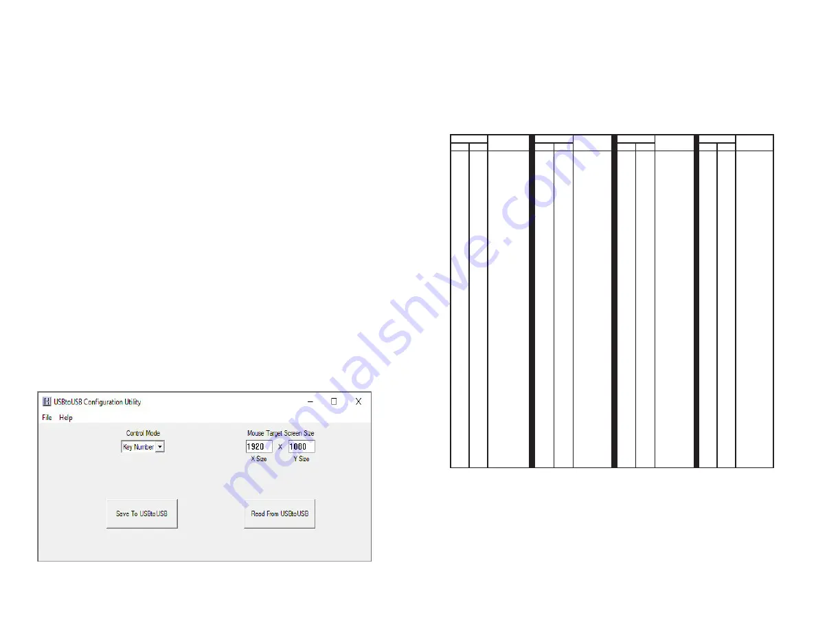
To configure the USBtoUSB, select the Control Mode from the
dropdown box to choose the conversion mode. Select between
ASCII (factory default), Extended ASCII, or Key Number Mode.
See pages 3-9 for a description of each of the control modes.
Next, enter the screen X and Y size for the target computer’s dis-
play settings. The X and Y sizes are used to set the USBtoUSB
internal storage such that the serial control for the mouse cursor
will better match the target system. When the USBtoUSB.exe pro-
gram is started, the X and Y values a are populated with the target
computer’s current display settings. The user may change these
if needed, but in general, the values selected by the program are
the proper values to be used. (See note on page 16)
Saving the Configuration to the USBtoUSB
Once the desired parameters have been set on the USBtoUSB
Configuration Utility Screen, it must be saved to the USBtoUSB unit to
begin operation according to those settings.
Select the button “Save To USBtoUSB” to write the configuration to
the unit. Once the configuration has been written, the USBtoUSB will
restart and begin operating according to the selected mode.


