7-28
SECTION 7 –
SPRAY SYSTEMS
6. Connect the solution line with the quick-
connect fittings (located beneath right-
hand side of machine).
7. The Rear Spray Boom is now ready for
use.
Removing the Rear Boom
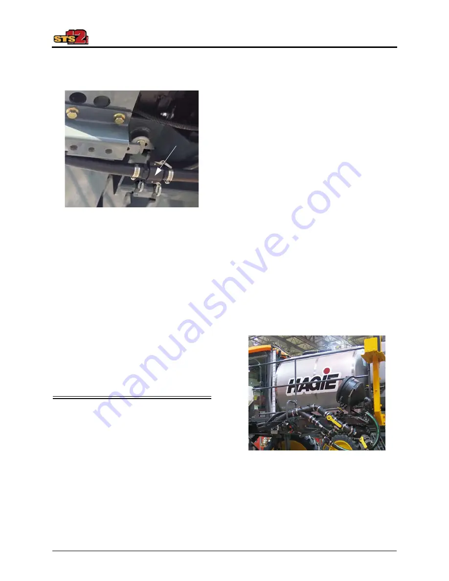
1. Disconnect the solution line from the
quick-connect fittings (G).
2. Unbolt the Rear Spray Boom (C) from
the Boom Mounting Brackets (D).
3. Remove the Rear Spray Boom and set
aside.
4. Route and reconnect solution line to the
front boom.
5. Rotate the 3-Way Boom Valve to the
HORIZONTAL position to route solu-
tion flow to the front boom.
SOLUTION SYSTEM
COMPONENTS
The Solution System is a constantly
monitored, continuously adjusted computer-
controlled system. The cab-mounted digital
spray system console receives information
from various inputs to help determine gallons
per acre (GPA)/liters per hectare (l/ha) and
gallons per minute (GPM)/liters per minute
(l/min).
Please read and understand the
information provided in this manual, as well
as the spray system console manufacturer’s
operation manual before operating the
Solution System. The following information
refers to components of the Solution System
and is not intended to replace the
manufacturer’s operating instructions.
•
Solution Tank
•
Solution Pump
•
Solution Pump Switch
•
Flow Meter
•
Pressure Gauge
•
Solution Tank Drain Valve
•
Solution Tank Valve
•
Main Tank Valve Switch
•
Agitation Valve
•
Agitation Valve Switch
•
Jet Agitators
•
Boom Solution Valve Switches
•
Section Indicator Display
•
Boom Solution Valve Indicators
(Transom), if equipped
•
Rate Control Switches
•
Pump Speed/Rate Switches
•
Master Spray Switch
•
Spray System Console
Solution Tank
Solution Pump
The Solution Pump (located near center of
machine) is a centrifugal-type hydraulic
pump that is controlled by the Solution Pump
Control Valve and the Spray System
Console.
-Typical View
G
Solution Tank
-Typical View
Summary of Contents for STS12i Combo
Page 276: ......


