background image

EQ45 GRADE 1 EXIT TRIM


INSTALLATION INSTRUCTIONS


I

-

ED02734


Rev 1, Rev Date: 01/12/2023


[27390110]


 Page 

2

 of 

8


Hager Companies  139 Victor Street, St. Louis, MO 63104   (800) 325

-

9995   www.hagerco.com


1


Safety Information


Carefully read the instructions before installing and using this lock.


WARNING: 

If the door needs to be drilled, be familiar with how to safely use your tools, and understand all the door preparation steps 

before proceeding.


FINISH & CARE NOTES: 

Either remove the locks or do not install them prior to painting your door to protect the finish. Periodically clean 

the locks with mild soap and a soft cloth. Do not use abrasives or harsh chemicals when cleaning or using the lock.


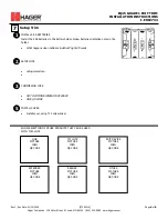
Required Tools


2


T10


PH2


PH3


OPTIONAL


OPTIONAL


3


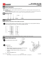
Prepare Door


Skip the prep steps if the door has already been prepared. 


1


NOTE

: Drill from both sides to avoid splintering the finished surface of wood doors. Not all holes are thru.


AA


Mark the Horizontal Centerline and Vertical Centerline on the door face based on the exit device installation instructions. 

Align the template and mark the door, drill the holes per template instructions.


4


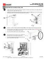
Remove back plate from Exit Escutcheon


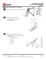
Prepare Exit Escutcheon


1


Hand Escutcheon


• 

Unstow the wires.


• 

Remove spring cage if necessary to orient arrows to match downward 

motion of the lever. Reattach with screws provided.


• 

Orient lever to desired handing. RHR shown, LHR opposite side of 

escutcheon


• 

Insert handing pin 

AA 

as shown.


2


Summary of Contents for EQ45

Page 1: ...chine 4 3 Power Pack Assy 1 4 AA Batteries 4 5 Screw Pack Power Pack Exit Trim 1 Screw 12 x 3 4 Pan Head Phillips Drive Sheet Metal 1 6 Main Gasket 1 7 Wire Harness Control to Reader Board 1 8 Instruc...

Page 2: ...brasives or harsh chemicals when cleaning or using the lock Required Tools 2 T10 PH2 PH3 OPTIONAL OPTIONAL 3 Prepare Door Skip the prep steps if the door has already been prepared 1 NOTE Drill from bo...

Page 3: ...in the Wire Harness 7 into the Reader Board as shown Prepare Exit Escutcheon Continued 3 Close up escutcheon and install Main Gasket Route wires through wiring hole shown Install Main Gasket 6 4 7 6...

Page 4: ...or using the 4 BB screws 1 4 20 x 3 4 provided and route the 2 Pin wire with black shrink wrap through the hole shown BB 1 5 Install Exit Trim and Power Pack RIM Black 2 Pin All Other Wires Wire Hole...

Page 5: ...black shrink wrap through the hole shown Install Exit Trim and Power Pack SVR 1 Plug the 2 6 and 8 Pin Extension harnesses 11 12 13 into their respective wires in the upper wire bundles Route the exte...

Page 6: ...orientation notes in the holder What happens when batteries installed Lights Sounds Setup Trim 1 SETUP LOCK Setup procedure 2 COMMISSION LOCK GO TO COMMISSIONING PROCEDURE GIVE QR CODE 3 SHOW SELECTIO...

Page 7: ...t on a circuit different from that to which the receiver is connected Consult the dealer or an experienced radio TV technician for help Changes or modifications to the device not expressly approved by...

Reviews: