background image

11. 

NON-USE PERIODS

During periods of extended non-use, the power cord should be unplugged from the power source.

12. CLEANING

The equipment should be cleaned only as detailed in the operating instructions.

13. OBJECT AND LIQUID ENTRY

Care should be taken so that objects and/or liquids, such as cleaning fluids or beverages, are not spilled into the
enclosure of the equipment.

14. 

DAMAGE REQUIRING SERVICE

Hafler equipment should be serviced by qualified service personnel when:

A.

The power supply cord or plug has been damaged, or

B.

Objects have fallen, or liquid has been spilled into the equipment, or

C.

The equipment has been exposed to rain, or

D .

The equipment does not appear to operate normally or exhibits a marked change in performance, or

E.

The equipment has been dropped, or the enclosure has been damaged.

15. SERVICING

The user should not attempt to service the equipment beyond that which is described in the operating instructions. All
other service should be referred to qualified service personnel.

16. CARTS AND STANDS

The equipment should be used with carts or stands only of sufficient strength and stability for the use intended.

An equipment and cart combination should be moved with care. Quick stops and starts, excessive force, and

uneven surfaces may cause the equipment and cart combination to topple.

-2-

Summary of Contents for 0915P

Page 1: ...Haflee H O M E A U D I O C O M P O N E N T S Series 0915 P R E A M P L I F I E R ...

Page 2: ... mount on a carpeted shelf or in a sealed enclosure Allow for proper clearance above the equipment WATER AND MOISTURE The equipment should not be used in or around water such as a bathtub sink or swimming area Also the equipment should not be used in areas prone to flooding such as a basement POWER SOURCES The equipment should be connected only to a power source of the same voltage and frequency a...

Page 3: ...d has been spilled into the equipment or C The equipment has been exposed to rain or D The equipment does not appear to operate normally or exhibits a marked change in performance or E The equipment has been dropped or the enclosure has been damaged 15 SERVICING The user should not attempt to service the equipment beyond that which is described in the operating instructions All other service shoul...

Page 4: ... 10 J FET Buffer And Record Output Driver 11 Tape Monitor Switching 11 Volume And Balance Controls 11 Line Amplifier 11 Tone Control System 11 Muting System 11 Power Supply 11 Headphone Amplifier 12 ADDITIONAL INFORMATION Installing Phono Option 12 Phono Board Installation Diagram 13 Installing Cartridge Loads 14 Changing Line Voltage Rating 14 Cartridge Loads Installation Diagram 15 General Troub...

Page 5: ...6 5 mV RMS INPUT IMPEDANCE Nominal 47 000 ohms Moving Magnet 220 pF as supplied user adjustable Moving Coil 100 ohms as supplied user adjustable GAIN 1 kHz Moving Magnet 38 5 dB Moving Coil 58 5 dB FREQUENCY RESPONSE 0 1 dB into 33 000 ohms BANDWIDTH 8 Hz 170 kHz 3 dB into 10k ohm load MAXIMUM OUTPUT 6 volts RMS TOTAL HARMONIC DISTORTION AND NOISE 008 2 volts RMS SENSITIVITY For 0 5 volts RMS Outp...

Page 6: ...sformers such as power amplifiers due to the possibility of audible hum or buzz from magnetic radiation The 915 Preamplifier is configurable for either 100 120 volt or 200 240 volt operation This is accomplished by changing internal jumpers on the printed circuit board The procedure is detailed in the section CHANGING LINE VOLTAGE RATING Make sure that the unit is configured for your local AC line...

Page 7: ...wer may be drawn from a single outlet or a combination of outlets Since some power amplifiers consume more than 1200 watts at maximum output check the power amplifier s rating before connecting to these convenience outlets The inputs labelled CD Tuner Video Aux 2 and Phono Aux 1 when the Phono Option is not installed are identical line level inputs The names chosen for these inputs are for conveni...

Page 8: ...MOUNT HOLES 19 VERSION ONLY TAPE MONITOR SWITCH TONE IN SWITCH OUTPUT OFF SWITCH READY LIGHT UP TO MONITOR TAPE INPUT UP TO ACTIVATE BASS TREBLE UP TO TURN OFF RED FOR MUTE ACTIVATED OUT1 OUT2 GREEN FOR OPERATE 915 PREAMPLIFIER FRONT PANEL VIEW lOO 120 VAC UNITS ONLY 200 240 VAC UNITS ARE WITHOUT CONVENIENCE OUTLETS POWER SWITCH CONTROLS PREAMPLIFIER POWER ...

Page 9: ...PHONO AUX 1 G R O U N D L I N E C O R D C O N N E C T O R SWITCHED OUTLETS OUTPUTS INPUTS T O P R O W R I G H T C H A N N E L BOTTOM ROW LEFT CHANNEL M C M M S W I T C H PHONO OPTION ONLY IN MOVING COIL OUT MOVING MAGNET 915 PREAMPLIFIER REAR PANEL VIEW 100 l 20 VAC UNITS ONLY 200 240 VAC UNITS ARE WITHOUT CONVENIENCE OUTLETS ...

Page 10: ...In Switch activates the Bass and Treble Controls when moved to the UP position In the DOWN position the Tone Controls are completely removed from the signal path regardless of Bass and Treble knob position The Bass Control has a variable inflection or hinge point so that only the very low frequencies are affected by small amounts of knob rotation on either side of center This facilitates small amo...

Page 11: ...Each Phono channel consists of six low noise JFET s connected in a complementary symmetry non differential configuration Shorted input moving coil equivalent input noise measures about 137 dB 140 nV wide band Only two stages are used to yield an open RIAA loop gain of about 110 dB in moving coil mode and 90 dB in moving magnet mode RIAA loop closure yields 58 5 dB and 38 5 dB respectively at 1 kHz...

Page 12: ...ath This switching is accomplished with the same type of CMOS FET electronic switch used for the Input Selector This switching arrangement eliminates signal degradation due to mechanical switch contacts and allows the electronic switch to be located very close to the Line Amplifier circuitry The Bass Control is of a moving inflection variable turnover type and the Treble Control is of a shelving v...

Page 13: ... from your Hafler Dealer Review the installation instructions before attempting this procedure If any doubts exist about one s ability to install the Phono Option it is advisable that the procedure be conducted by a qualified technician WARNING UNPLUG THE UNIT FROM AC POWER BEFORE ATTEMPTING THIS PROCEDURE FAILURE TO DO SO CAN RESULT IN SEVERE ELECTRICAL SHOCK AS WELL AS DAMAGE TO THE PREAMPLIFIER...

Page 14: ...PLASTIC BUTTON T PHONO PC BOARD MAIN PC BOARD 4 PIN CONNECTORS PLASTIC STANDOFFS INSTALLATION OF OPTIONAL PHONO PRINTED CIRCUIT BOARD ...

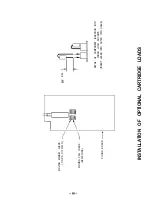
Page 15: ...ecurely mate to the sockets Be sure not to stress the component lead where it enters the body of the part Observe carefully which sockets are for MM capacitors and for MC resistors 3 Replace cover NOTE Even while experimenting with different optional loads the cover must be replaced before re applying AC power not only for safety reasons but to shield hum and interference which can totally invalid...

Page 16: ...ET LOADS C A P A C I T O R S MOVING COIL LOADS 1 RESISTORS PHONO BOARD 3181 3181 MAX DETAIL OF COMPONENT INSERTION INTO PHONO LOAD SOCKETS INSERT LEADS INTO OUTER TWO HOLES INSTALLATION OF OPTIONAL CARTRIDGE LOADS ...

Page 17: ...wner The 915 Preamplifier is configured for normal operation when all toggle switches are in the down position That is Tape Monitor is NOT selected Tone Controls are OFF and the outputs are ON If no sound is heard from the system first check the position of the Tape Monitor and Output switches If altered tonal balance is detected even with the Bass and Treble controls centered check the position o...

Page 18: ...ectrically live chassis Therefore this method of ground isolation should be employed only when absolutely necessary rather than as a general practice When using a ground adaptor for isolation make sure that the power cord plug is inserted into the receptacle in the same orientation as if no adaptor were present to maintain the same hot neutral polarity SPECIAL NOTE ON VIDEO CABLE GROUNDS As mentio...

Page 19: ...I t I 915 PREAMPLIFIER FUNCTIONAL BLOCK DIAGRAM ONE CHANNEL SHOWN PHONO OPTION INSTALLED ...

Page 20: ...04 Q5 Q105 Q6 Q106 Q7 Q8 0 SW1 SW2 SW3 SW4 2SK163 Graded 2SK163 Graded 2SK163 2SK163 2SK163 2SJ74 BC560C BC560C BC560C BC550C Rotary Switch Toggle Switch Toggle Switch Power Switch SW5 SW1 05 Toggle Switch RLY1 RLY2 Relay Relay VR1 VR101 VR2 VR102 VR3 VR103 VR4 VR104 Volume Control Balance Control Bass Control Treble Control LED1 Tri Color LED J1 J3 J 4 J5 J9 J10 4 Pin Header IEC Connector Conveni...

Page 21: ...wvuwla mom lN3NOdW03 awoa mm13 NIVW NOlldO ONOHd LIOA CY tl P r 21 nqy 1 10 u us I I I I I ...

Page 22: ...A B 100 12OVW c 200 240 VAE rJoba i 1 L A D 7 1N5226B Bci D6 i lN4145 RlQ 1OK 1 15V di PWNOOPllONJUMPERS PHONOPWER1 K 4 15V 15V L C H hL CH Rl 15V ...

Page 23: ...RIGHT CHANNEL ONLY SHOWN 2 COMPONENT DESIGNATORS 1 99 F O R COMMON AND RIGHT CHANNEL PARTS 100 199 FUR L E F T CHANNEL 5 ML RESISTORS IN OHMS CAPACITORS IN M I C R O F A R A D S 4 TCNE5WllCHSHWNINBYPASSPO5RlCN 5 TAPE MONITOR SWITCH S H O W N IN WE POSITION 6 MUERW AY5lUWNINUNMUTEDPDSnlDN ...

Page 24: ...04 2SJ72 Q5 Q105 2SJ74 Q6 Q106 2SK163 SW1 SW1 01 4PDT Switch J1 J3 4 Pin Receptacle RMP 4 6810 RMP 8 0332LN RMP 8 0332LN RMP 4 6810 RMP 4 2672 RMP 4 3323 RMP 4 4752 RMP 4 3160 RMP 4 1000 RMP 8 0332LN RMP 4 3324 RMP 4 1001 RMP 4 2215 RMP 4 1005 RMP 4 3160 RMP 4 3324 RMP 4 1001 RMP 4 2215 RMP 4 1005 RMP 4 3160 SSH 674 SSH 674 SSH 617C SSH 617C SSH 617D SSH 614 SWH 125 CCH 240 All Capacitors In Micro...

Page 25: ... 1 0 2 I I I 11 4 4 a a En En R1B05 R1B05 c5 c5 R R 13 13 0 1 0 4 0 1 0 4 R l 1 8 R l 1 8 OS OS ii ii R l 1 3 R l 1 3 jRSo jRSo f oRll f oRll Rl9 Rl9 R6 R6 Rl4 Rl4 Rfli Rl150 Rl150 BfWOd BfWOd Rll9 Rll9 R 1 0 8 R 1 0 8 R l 1 4 R l 1 4 J3 J3 11 I I 4 4 52 52 4 4 PHONO BOARD COMPONENT LAYOUT DIAGRAM 23 ...

Page 26: ...WER R 1 8 II I B 22 1M PHONO OUTPUT 06 2SK163 QR 2 0 316 1 RIGHT CHANNEL ONLY SHOWN 2 COMPONENT DESIGNATORS 1 99 FOR RIGHT CHANNEL PARTS 1 W 199 FOR LEFT CHANNEL 3 ALL RESISTORS IN OHMS CAPACITORS IN MICROFARADS 4 MC MM SWITCH SHOWN IN MOVING MAGNET POSITION PHONO BOARD CIRCUIT SCHEMATIC DIAGRAM ...

Page 27: ...en years from the date of purchase including parts labor and return shipping costs within the Continental United States This warranty applies only to products sold in the United States Of America For warranties outside the USA please contact your local agent It is the owner s responsibility to pay shipping preferably United Parcel Service UPS to the factory collect shipments will not be accepted U...

Reviews: