6
OPERATION MANUAL
OPERATION
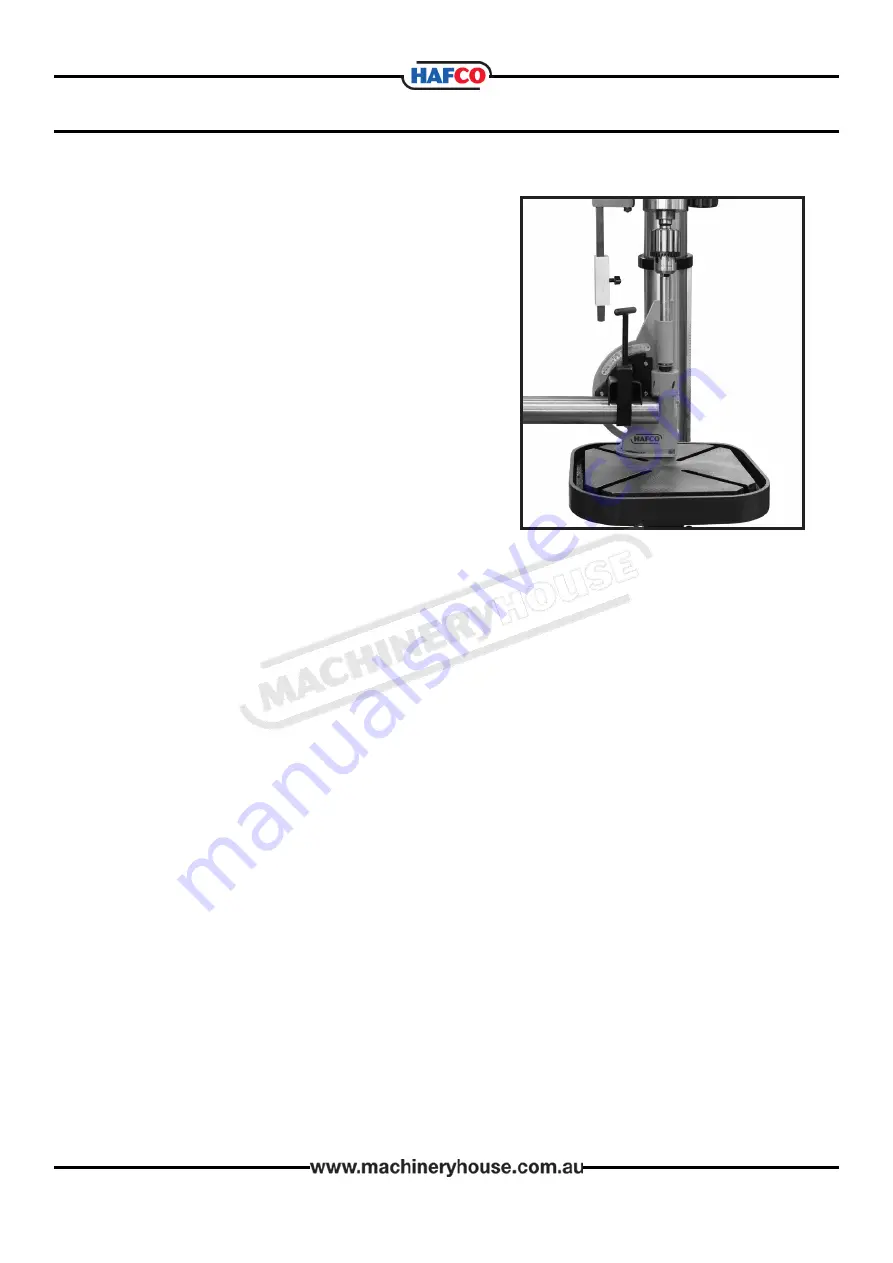
1. Insert the tubing you wish to cut in the Clamp
Assembly (1#), underneath the inverted “V”. The
inverted “‘V” feature of the clamp will hold your
tubing (up to 2” long) in place. Do not insert the
tubing more than half of its length. When cutting
in severe angles, only insert the tubing far enough
to start the cut. Secure the tubing in place using
the Handle Clamp Screw Assembly (2#).
2. Set the speed of your drill press to approximately
500 rpm for most materials. When cutting thin
wall, hard alloy tubing such as chrome-molly,
higher speeds will be required. When cutting
softer, coarser materials, use slower speeds.
NOTE: Practice on scrap material before making cuts on
your work material.
3. As you work, lubricate the hole saw and bushings with cutting oil to extend service life.
4. When doing severe angle cuts with large diameter tubing, you will need to put the Spindle
Support (6#) in its uppermost position in order to accommodate its size. However, you
should always position the Spindle Support (6#) as low as possible to preserve accuracy.
To move the Spindle Support (6#), simply loosen the two Bolts (16#) that affix it to the Body
(13#) reposition and secure the Bolts (16#).
5. To adjust the angle of the clamp, loosen the Bolts (15#) that secure it to the Body (13#),
proceed to the desired angle on the Angle Indicator (10#), and re tighten the Bolts (15#).
6. When the tube is clamped in the Pipe/Tube Notcher and the angle is properly set, you can
proceed to cut the workpiece.
7. To remove the blade or bit, shut off the drill press, insert the locking pin (14#) into the
spindle support(6#), and remove the bit.
MAINTENANCE
1. Please observe good shop practices for your safety and to extend the work life of your tools.
2. Periodically brush away cuttings and debris from the Pipe/Tube Notcher, especially the
bushings and spindle area to avoid scoring or binding these components.
3. Use a suitable light grease on the bushings to prevent overheating and wear.
4. When cutting metal tubes, use plenty of cutting fluid to prevent tool or material
overheating, and to remove cuttings from the work area.
5. Be sure to carefully align the drill press spindle and the Pipe/Tube Notcher spindle to
prevent binding.
6. After use, clean the Pipe/Tube Notcher, and apply a light lubrication to all moving parts and
unpainted metal to prevent rust.
7. Leave the Locking Pin (14#) in place in the Spindle Support (16#) when moving or storing
this fixture.
8. Store the Pipe/Tube Notcher covered and in a dry, dust free place.
9. Help avoid injury by preventing access to this tool by unauthorized persons and children.


