Installation
Seite 32 von 38
QSL-T/QST-150-25/45 V3
Standard
Original operating manual
Rev1.1
4. Installation
4.1
General
Check motor
Vor Inbetriebnahme des Motors muss dieser auf Isolationsfehler und Beschädigungen durch
Transport/Montage geprüft werden.
CAUTION
Injury/ Damage
Due to insulation defects caused by transport / assembly
The electrical supply lines and the motor windings may not be damaged. If there is a visible
damage, the engine must be stopped immediately and the motor should be sent to the
manufacturer for inspection.
4.2
Mechanical assembly
Assembly motor
Assembly of drive output
Attachment
4x M6 auf TKØ75mm
6x M6 auf TKØ40mm
Min. screw-in depth
12mm
6mm
Max. screw-in depth
18mm
10mm
Max. tightening torque*
11,3Nm
11,3Nm
* The maximum tightening torque specified above relates to screws with a property class of at least 8.8
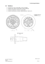
To center the attachment to be mounted, we recommend Ø 21H7(see chapter 3.2)
Use a suitable screw lock to prevent the screw connections from loosening during operation.
WARNING
Injuries
Due to unsuitable attachments
By attaching unbalanced components and / or sharp / dangerous components the motor
can be damaged when in operation and can become a source of danger for injuries.
Only balanced attachments that do not have any sharp edges or dangerous geometries
must be used. Attachment parts must only be attached via the drive shaft that is intended
for this.
HINT
The above-mentioned maximum screw-in depth in the shaft must never be exceeded,
otherwise the front ball bearing can be damaged.
INFORMATION
The motor can only be operated with a BLDC controller of the HST-series proved by us. If
non-approved controllers are used, no guarantee can be given for damage caused by third-
party products.


