


Problem
Possible cause
Solution
The sensor status LED
stays off, but the second
sensor operates.
Sensor connection issue
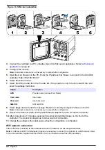
Examine the sensor and the sensor cable for
damage. If damage is found, contact technical
support.
If no damage is found, disconnect the sensor, wait
for 15 seconds, then connect the sensor again.
Contact technical support if the LED stays off again.
The sensor status LED
flashes amber, while the
second sensor is not
connected.
Sensor connection issue
Examine the sensor and the sensor cable for
damage. If damage is found, contact technical
support.
If no damage is found, disconnect the sensor, wait
for 15 seconds, then connect the sensor again.
Contact technical support if the LED flashes amber
again.
Connection problems
Problem
Possible cause
Solution
The cloud connection LED
stays red.
No access to cloud,
but access to
internet
If the controller is connected first time to cloud, make sure
that the controller is provisioned by the MSM.
If the controller was connected to the cloud before, set the
controller to off. Set the controller to on again. Contact
technical support if the LED stays red again.
The cloud connection LED
stays off. Sometimes the
LED flashes blue for a short
time.
No access to internet Cellular internet access:
• Use the web server application to check the SIM card
settings (provider, APN etc.).
• Use the web server application to check the network
status.
• Make sure that the prepaid SIM card has credit.
• Make sure that the SIM card data volume is not
exceeded.
LAN internet access:
• Make sure that the controller has approval to be
connected in the network.
• Make sure that the network cable is connected to the
correct Ethernet port. Refer to
• Use the web server application to examine the network
status.
The cloud
connection LED is
not working.
Make sure that the sensors are connected to MSM.
Contact technical support.
Replacement parts and accessories
W A R N I N G
Personal injury hazard. Use of non-approved parts may cause personal injury, damage to the
instrument or equipment malfunction. The replacement parts in this section are approved by the
manufacturer.
Note: Product and Article numbers may vary for some selling regions. Contact the appropriate distributor or refer to
the company website for contact information.
30
English
Summary of Contents for SC4200c
Page 1: ...DOC343 52 90586 SC4200c 06 2019 Edition 7 User Manual...
Page 2: ......
Page 34: ...32 English...
Page 35: ......


