


After the plug-in expansion card is installed and connected, configure the card. Refer to the
documentation supplied with the Profibus DP card.
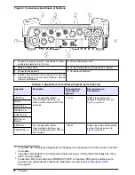
Figure 10 Profibus DP card (YAB103 since December 2013) connections
1
Wiring information—Profibus outputs
4
Network termination activated–last device on
network
2
Profibus DP card
5
Network termination deactivated–other devices on
network after this device
3
Terminal Block–Refer to
Table 6
for terminal
assignments
Table 6 Profibus DP card (YAB103) terminal descriptions
Terminal
Description
Wire color
1
B2 out
Red
2
A2 out
Green
3
5 V
Not used
4
0 V
Not used
5
B1 in
Red
6
A1 in
Green
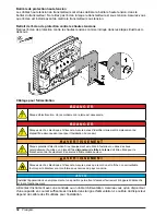
Remove an expansion card
Remove an expansion card if the probe connectors are blocked. Refer to the SC controller Profibus
DP/V1 network card documentation.
Note: The compact connectors are a very tight fit and the connections can easily break. Do not apply too much
force to remove the compact connectors.
1.
Delete the card in the SC controller.
2.
Remove power from the instrument.
3.
Remove the probe module cover. Refer to
Remove the cover
on page 10
4.
Disconnect all of the wires from the card.
English
17
Summary of Contents for SC1500
Page 2: ...English 3 Fran ais 23 Espa ol 45 67 2...
Page 68: ...ESD 68...
Page 69: ...sc1500 1 4 20 mA iOS Android LAN Wi Fi 1 1 USB 81 5 2 USB 6 3 1 7 4 sc1500 8 6 72 1 83 2 69...
Page 70: ...2 1 sc1500 3 USB 2 2 3 4 3 2 40 mm 1 57 in 70...
Page 71: ...USB USB sc1500 USB USB 4 5 40 mm 1 57 in 4 USB 5 USB 6 2 2 71...
Page 73: ...73...
Page 74: ...3 m 10 ft 1 5 mm2 15 AWG 300 VAC 70 C 158 F 74...
Page 75: ...3 m 10 ft 70 C 158 F 1 5 mm2 15 AWG 7 3 7 1 3 2 4 75...
Page 77: ...4 1 1 NC 7 3 NC 2 1 8 3 3 1 NO 9 3 NO 4 2 NC 10 4 NC 5 2 11 4 6 2 NO 12 4 NO NC NO 77...
Page 78: ...4 20 mA 8 5 pH 500 15 26 AWG 8 1 3 2 5 1 1 6 3 2 1 7 4 3 2 8 4 4 2 9 5 3 78...
Page 81: ...11 6 72 100 240 V 11 USB USB Modbus TCP IP Modbus TCP IP Modbus TCP IP TCP IP M2M 81...
Page 85: ......