6
General Information
1.2.2 Safety precautions
•
The power cord plug connection is also used as a main power switch.
•
The instrument must be connected to an electrical system which complies with
applicable local regulations.
•
All the cables connected to the instrument must be fire resistant, type UL94V-1
•
The operator must read and understand this manual before using the instrument.
•
The instrument will not be used as a safety device. It does not provide a security
function in a hazardous process.
1.2.3 Service and repairs
None of the analyzer’s components can be serviced by the user. Only personnel from Hach or
its approved representative(s) is (are) authorized to attempt repairs to the system and only
components formally approved by the manufacturer should be used. Any attempt at repairing
the analyzer in contravention of these principles could cause damage to the analyzer and
corporal injury to the person carrying out the repair. It renders the warranty null and void and
could compromise the correct working of the analyzer and the electrical integrity or the CE
compliance of the analyzer.
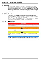
DANGER
Always remove power from the controller before performing maintenance activities.
WARNING
Potential Electrocution Hazard. Always disconnect power to the instrument when
making electrical connections.
WARNING
Potential Electrocution Hazard. If this equipment is used outdoors or in potentially
wet locations a
Ground Fault Interrupt
device must be used for connecting the
equipment to its main power source.
WARNING
Potential Electrocution Hazard. Connect only safety low voltage < 33 VAC RMS.
CAUTION
Personal Injury Hazard. Only qualified personnel should conduct the tasks described in this
manual.
NOTICE
Install the device in a location and position that gives easy access to the disconnect device
and its operation.
NOTICE
Potential Instrument Damage. Delicate internal electronic components can be
damaged by static electricity, resulting in degraded performance or eventual failure.
Summary of Contents for ORBISPHERE K1200
Page 5: ...4 Table of Contents...
Page 13: ...12 General Information...
Page 39: ...38 Installation...
Page 45: ...44 User Interface...
Page 46: ...45 Section 5 View Menu Figure 34 View menu...
Page 49: ...48 View Menu...
Page 59: ...58 Calibration Menu...
Page 60: ...59 Section 8 Inputs Outputs Menu Figure 40 Inputs Outputs menu...
Page 62: ...61 Inputs Outputs Menu 8 4 Analog outputs Figure 41 Analog outputs menu...
Page 69: ...68 Inputs Outputs Menu...
Page 86: ...85 Section 11 Products Menu Figure 44 Products menu...
Page 89: ...88 Global Configuration Menu...
Page 90: ...89 Section 13 Services Menu Figure 46 Services menu Part 1...
Page 91: ...90 Services Menu Figure 47 Services menu Part 2...


