4.1 Measurement window
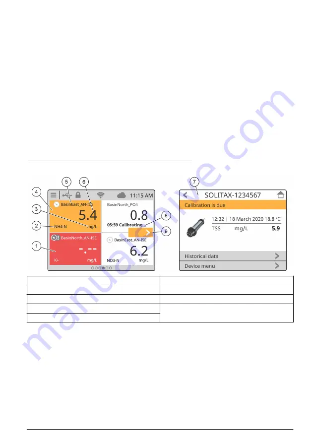
The main screen shows the measurement window. The carousel icon shows at the bottom of the
main screen when there are other screen views available. Each screen view has one, two or four
measurement windows, based on the connected sensors and the parameters of each sensor. The
controller automatically fills the measurement windows to show all of the information for the
connected devices. The measurement window shows the data that follows:
• Name, value, parameter and unit of the measurement device
Note: Measurement devices are the connected digital sensors, analog sensors or 4-20 mA inputs from external
devices.
• Sensor errors and warnings. If the measurement window background color is amber, there is a
warning for the sensor. If the measurement window background color is red, there is an error for
the sensor. A small icon shows when the error or warning is in a different screen view. Swipe left
or right to go the screen with the error or warning, or push the icon to go directly to the device
detail window. When the sensor is not in operation, the inactive condition shows on the
measurement window.
• Prognosys (if available). The Prognosys icon shows when there is no issue or maintenance
planned, or if maintenance is due or scheduled. Go to the device detail window to see more
Prognosys information.
• The task in operation (maintenance or calibration task)
Figure 14 Measurement window and device detail screen
1
Sensor error
6
Measured value
2
Device parameter
7
Device detail screen
3
Units
8
Task
4
Sensor warning
9
Error or warning in a different screen view.
5
Device name
Section 5 Startup
Connect the power cord to an electrical outlet with protective earth ground or set the circuit breaker
for the controller to on.
English
23
Summary of Contents for LXV525.99A15551
Page 1: ...DOC343 52 90690 SC4500 08 2022 Edition 3 User Manual ...
Page 2: ......
Page 26: ...5 1 Menu structure 24 English ...
Page 63: ......


