background image

1

2

3

4

62


Français

Summary of Contents for LANGE HIAC 9703+

Page 1: ...DOC026 98 80097 HIAC 9703 Liquid Particle Counter 06 2010 Edition 2 User Manual Bedienungsanleitung Manuale operativo Manuel de l utilisateur Manual del usuario...

Page 2: ...English 3 Deutsch 20 Italiano 37 Fran ais 54 Espa ol 71 2...

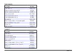
Page 3: ...2 mm 0 047 in ID 1 57 mL for 14 cm 5 5 in large bore Sensor concentration limits particle per ml HRLD150 18 000 HRLD150JA 18 000 HRLD400 10 000 HRLD600JS 6 000 MC05 9 000 Wetted materials PTFE Teflon...

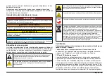
Page 4: ...f in European public disposal systems after 12 August of 2005 In conformity with European local and national regulations EU Directive 2002 98 EC European electrical equipment users must now return old...

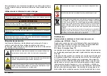
Page 5: ...sure to the beam of a Class 1 laser will not result in eye injury Class 1 lasers may therefore be considered safe However Class 1 laser products may contain laser systems of a higher class but there a...

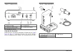
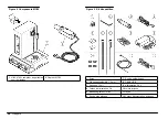
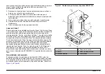
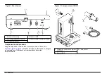
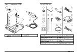
Page 6: ...r Product components Make sure that all components have been received Refer to Figure 3 Figure 4 and Figure 5 If any items are missing or damaged contact the manufacturer or a sales representative imm...

Page 7: ...rticle counter 2 Sensor MC05 Figure 5 Shipping kit 1 Nut 7 Probe small bore 2 Hex Key 1 5 mm 8 Cable USB 3 Syringe 10 ml 9 Power supply 24V 4 Power cord AC 10 O rings 5 Stir Bar Teflon 11 Tubing 6 Pro...

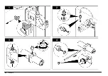
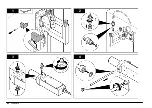
Page 8: ...nd near an electrical outlet and a computer Make sure the power switch is accessible Install the HRLD or MC05 sensor The sensor is held in place by the holding arm A sampling probe and tubing must con...

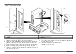
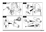
Page 9: ...1 2 3 4 English 9...

Page 10: ...5 7 6 10 English...

Page 11: ...1 2 3 4 English 11...

Page 12: ...5 7 6 12 English...

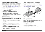
Page 13: ...al environmental regulations Install or remove the docking module Docking modules are available for single or multiple container sampling Install the small vial clamp The optional small vial clamp con...

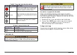
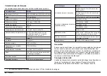
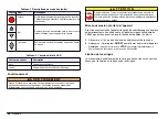
Page 14: ...the bottom plate on the module enclosure and install the four screws User interface The buttons on the front panel allow the user to operate the syringe sample probe and stirrer Refer to Figure 6 Tabl...

Page 15: ...r explosion C A U T I O N Chemical hazard Always follow appropriate laboratory safety procedures when chemicals are handled Always wear all personal protective equipment appropriate to the chemicals u...

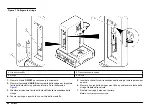
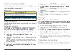
Page 16: ...he plunger bolt from the syringe drive 4 Hold the syringe and push the bolt through the plunger hole 5 Push the bolt in the syringe drive hole and turn the bolt by hand to tighten 6 Pull the syringe b...

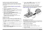
Page 17: ...liquid under the sample probe 3 Push the LIFT LOWER button to lower the sample probe in the flushing liquid 4 Push the CLEAN button The syringe fills with the flushing liquid and pushes the liquid ou...

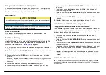
Page 18: ...eionized water on the docking module 8 Push the LIFT LOWER button to lower the sample probe 9 Push the CLEAN button to flush the syringe with the rinse water 10 Repeat the flush with rinse water for a...

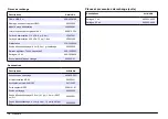
Page 19: ...ption Item no Cleaning floss 660 850 0001 MC05 Accessory kit 089206 11 MC05 Modified coupling 047156 03 MC05 Sensor holder 2089191 01 Probe cleaning 90450003 Sampling probe 15 4 cm 6 1 in 1 2 mm 0 047...

Page 20: ...15 4 cm 6 1 Zoll 1 2 mm 0 047 Zoll ID 1 57 mL f r 14 cm 5 5 Zoll gro e Bohrung Sensorkonzentrationsgrenzwerte Partikel pro mL HRLD150 18 000 HRLD150JA 18 000 HRLD400 10 000 HRLD600JS 6 000 MC05 9 000...

Page 21: ...Elektrizit t besch digt werden was zu Beeintr chtigungen der Ger teleistung bis hin zum Ausfall des Ger tes f hren kann Dieses Symbol zeigt an dass eine Lasereinheit in diesem Ger t verwendet wird Di...

Page 22: ...Klasse 1 sind Produkte deren abgestrahlte Leistung des Laserstrahls die zug ngliche Strahlung immer unter dem maximal zul ssigen Expositionsgrenzwert liegt Daher liegt die Ausgangsleistung von Lasern...

Page 23: ...ten Stellen Sie sicher dass Sie alle Teile erhalten haben Siehe Abbildung 3 Abbildung 4 und Abbildung 5 Wenn irgendwelche Posten fehlen oder besch digt sind kontaktieren Sie bitte sofort den Herstelle...

Page 24: ...2 Sensor MC05 Abbildung 5 Versandsatz 1 Mutter 7 Ansaugrohr kleiner Durchmesser 2 Sechskantschl ssel 1 5 mm 8 Kabel USB 3 Spritze 10 ml 9 Netzteil 24 V 4 Netzkabel 10 O Ringe 5 R hrfisch Teflon 11 Abl...

Page 25: ...Steckdose und ein Computer in der N he befinden Achten Sie darauf dass der Netzschalter zug nglich ist Montage des HRLD oder MC05 Sensors Der Sensor wird durch einen Arm gehalten Um einen Probendurch...

Page 26: ...1 2 3 4 26 Deutsch...

Page 27: ...5 7 6 Deutsch 27...

Page 28: ...1 2 3 4 28 Deutsch...

Page 29: ...5 7 6 Deutsch 29...

Page 30: ...Fl ssigkeit entsprechend der geltenden staatlichen bundesstaatlichen oder lokalen Vorschriften Ein oder Ausbau des Dockingmoduls Dockingmodule sind f r einzelne oder mehrere Probenbeh lter lieferbar...

Page 31: ...den Magnetr hrer 5 Legen Sie die Bodenplatte auf dem Modulgeh use auf und befestigen Sie die vier Schrauben Benutzeroberfl che Mit den Tasten an der Frontseite k nnen Spritze Ansaugrohr und Magnetr h...

Page 32: ...einer Explosion f hren V O R S I C H T Gefahren durch Chemikalien Befolgen Sie beim Umgang mit Chemikalien immer die einschl gigen Laborsicherheitsvorschriften Tragen Sie immer pers nliche Schutzausr...

Page 33: ...iehe Abbildung 7 3 L sen Sie die Kolbenschraube aus dem Spritzenantrieb und nehmen Sie sie heraus 4 Halten Sie die Spritze und dr cken Sie die Schraube durch die Bohrung im Kolben 5 Dr cken Sie die Sc...

Page 34: ...ige wenige Zyklen Sp len Sie die Spritze nach Gebrauch mit destilliertem oder entionisiertem Wasser aus 1 Dr cken Sie die Taste LIFT LOWER um das Ansaugrohr nach oben zu bewegen 2 Stellen Sie den Beh...

Page 35: ...e die Kolbendichtung mit entionisiertem Wasser an 4 Belassen Sie die L sung mindestens 30 Minuten in der Spritze 5 Dr cken Sie die Taste LOAD um die Reinigungsl sung ber den Ablauf abzulassen 6 Dr cke...

Page 36: ...5 5 Zoll gro e Bohrung 90620008 R hrfisch Teflon 5 Stck je Packung 600 100 0003 Spritze 10 ml 690 300 4808 Schlaucheinheit Ablauf 089208 01 Zubeh r Beschreibung Bestellnr Reinigungsband 660 850 0001 M...

Page 37: ...ml HRLD150 18 000 HRLD150JA 18 000 HRLD400 10 000 HRLD600JS 6000 MC05 9000 Materiali bagnati PTFE Teflon TFE Teflon PFA Teflon Kel F acciaio inossidabile 316 vetro Viton Numero di canali 4 2 per dispe...

Page 38: ...e occhiali protettivi Gli apparecchi elettrici marcati con questo simbolo potrebbero non essere smaltiti nei sistemi di smaltimento pubblici europei dopo il 12 agosto 2005 In conformit ai regolamenti...

Page 39: ...ni oculari L esposizione ai raggi laser di classe 1 non causa di lesioni agli occhi I laser di classe 1 possono pertanto essere considerati sicuri Tuttavia i prodotti laser di classe 1 possono contene...

Page 40: ...nenti del prodotto Accertarsi che tutti i componenti siano stati ricevuti Fare riferimento a Figura 3 Figura 4 e Figura 5 In caso manchi un componente o si notino eventuali danni contattare immediatam...

Page 41: ...Figura 5 Kit di spedizione 1 Dado 7 Sonda diametro piccolo 2 Chiave esagonale 1 5 mm 8 Cavo USB 3 Siringa 10 ml 9 Alimentazione 24V 4 Cavo di alimentazione US 10 Anelli toroidali 5 Barra di miscelazi...

Page 42: ...elettrica e a un computer Accertarsi che l interruttore di alimentazione sia accessibile Installare il sensore HRLD o MC05 Il sensore tenuto in posizione dal braccio di supporto Una sonda e un tubo di...

Page 43: ...1 2 3 4 Italiano 43...

Page 44: ...5 7 6 44 Italiano...

Page 45: ...1 2 3 4 Italiano 45...

Page 46: ...5 7 6 46 Italiano...

Page 47: ...do la normativa ambientale locale statale e nazionale Installare o rimuovere il modulo di alloggiamento I moduli di alloggiamento sono disponibili per campionamento con contenitori singoli o multipli...

Page 48: ...o 5 Posizionare la piastra inferiore sull involucro del modulo e collocare le quattro viti Interfaccia utente I pulsanti sul pannello anteriore consentono all utente di utilizzare la siringa la sonda...

Page 49: ...di o esplosioni A T T E N Z I O N E Pericolo di origine chimica Seguire sempre le procedure di sicurezza del laboratorio appropriate nella gestione di prodotti chimici Indossare sempre tutte le appare...

Page 50: ...e inferiore Fare riferimento a Figura 7 3 Allentare e rimuovere la vite dello stantuffo dalla trasmissione della siringa 4 Tenere la siringa e inserire la vite nel foro dello stantuffo 5 Inserita la v...

Page 51: ...i qualche ciclo senza liquido Sanitizzare accuratamente la siringa con acqua distillata o deionizzata dopo l uso 1 Spingere il pulsante SOLLEVA ABBASSA per sollevare la sonda del campione 2 Posizionar...

Page 52: ...zzata 4 Lasciare la soluzione nella siringa per almeno 30 minuti 5 Premere il pulsante CARICA per inviare la soluzione pulente allo scarico 6 Spingere il pulsante SOLLEVA ABBASSA per sollevare la sond...

Page 53: ...da di campionamento 14 cm diametro grande 90620008 Barra di miscelazione Teflon conf 5 600 100 0003 Siringa 10 ml 690 300 4808 Tubazioni scarico 089208 01 Accessori Descrizione Prodotto n Fibra pulent...

Page 54: ...172 mL pour 15 4 cm 6 1 po 1 2 mm 0 047 po D I 1 57 mL pour 14 cm 5 5 po gros al sage Limites de concentration de capteur particules par mL HRLD150 18 000 HRLD150JA 18 000 HRLD400 10 000 HRLD600JS 6...

Page 55: ...ui risque d alt rer ses performances et son fonctionnement Ce symbole indique qu un dispositif laser est utilis dans l quipement Ce symbole indique la n cessit de porter des lunettes de protection L q...

Page 56: ...maximale autoris e La puissance de sortie des LASERS de classe 1 est inf rieure au niveau consid r nocif pour les yeux L exposition au faisceau d un LASER de classe 1 ne pr sente pas de danger pour l...

Page 57: ...eur Composants du produit S assurer qu avoir re u tous les composants Reportez vous Figure 3 Figure 4 et Figure 5 Si des l ments manquent ou sont endommag s contactez imm diatement le fabricant ou un...

Page 58: ...MC05 Figure 5 Kit d exp dition 1 Ecrou 7 Sonde petit al sage 2 Cl hexagonale m le 1 5 mm 8 C ble USB 3 Seringue 10 ml 9 Alimentation 24 V 4 Cordon d alimentation CA 10 Joints toriques 5 Barreau agita...

Page 59: ...teur S assurer que l interrupteur d alimentation est accessible Mise en place du capteur HRLD ou MC05 Le capteur est maintenu en place par le bras de maintien Une sonde d chantillonnage et une canalis...

Page 60: ...1 2 3 4 60 Fran ais...

Page 61: ...5 7 6 Fran ais 61...

Page 62: ...1 2 3 4 62 Fran ais...

Page 63: ...5 7 6 Fran ais 63...

Page 64: ...les d chets conform ment aux r glementations locales d tat et nationales de protection de l environnement Mise en place ou d pose du module d accueil Les modules d accueil sont propos s pour chantillo...

Page 65: ...a plaque inf rieure sur l enveloppe du module et mettre en place les quatre vis Interface utilisateur Les touches de la face avant permettent l utilisateur d actionner la seringue la sonde d chantillo...

Page 66: ...losion A T T E N T I O N Danger chimique Toujours respecter les proc dures de s curit de laboratoire appropri es pour la manipulation des produits chimiques Toujours porter les quipements de protectio...

Page 67: ...le plus bas Reportez vous Figure 7 3 Desserrer et d poser la vis du piston de l entra nement de la seringue 4 Maintenir la seringue et pousser la vis travers le trou du piston 5 Pousser la vis dans l...

Page 68: ...s cycles sans liquide Rincer soigneusement la seringue l eau distill e ou d min ralis e apr s utilisation 1 Appuyer sur la touche LIFT LOWER pour monter la sonde d chantillon 2 Placer le r cipient con...

Page 69: ...olution dans la seringue au minimum 30 minutes 5 Appuyer sur la touche LOAD pour envoyer la solution de nettoyage vers l vacuation 6 Appuyer sur la touche LIFT LOWER pour monter la sonde d chantillon...

Page 70: ...Barreau agitateur Teflon paquet de 5 600 100 0003 Seringue 10 ml 690 300 4808 Ensemble canalisation vidange 089208 01 Accessoires Descriptions Article No Accessoire de nettoyage 660 850 0001 Kit d ac...

Page 71: ...pulg 1 2 mm 0 047 pulg ID 0 172 ml para 15 4 cm 6 1 pulg 1 2 mm 0 047 pulg ID 1 57 ml para 14 cm 5 5 pulg di metro interior grande L mites de concentraci n del sensor part culas por ml HRLD150 18 000...

Page 72: ...dr desechar por medio de los sistemas europeos p blicos de eliminaci n despu s del 12 de agosto de 2005 En cumplimiento de las reglamentaciones nacionales y locales directiva europea 2002 98 CE los us...

Page 73: ...onsidera que puede producir da os oculares La exposici n al haz de un l ser de Clase 1 no causar lesiones oculares Por lo tanto los l ser de Clase 1 pueden ser considerados seguros Sin embargo los pro...

Page 74: ...r Componentes del producto Aseg rese de haber recibido todos los componentes Consulte la Figura 3 Figura 4 y Figura 5 Si faltan art culos o est n da ados p ngase en contacto con el fabricante o el rep...

Page 75: ...a 5 Kit de env o 1 Tuerca 7 Sonda di metro interior peque o 2 Llave hexagonal 1 5 mm 8 Cable USB 3 Jeringa 10 ml 9 Fuente de alimentaci n 24 V 4 Cable de alimentaci n CA 10 Juntas t ricas 5 Barra de a...

Page 76: ...trica y un ordenador Aseg rese de que se puede acceder al interruptor de encendido Instalar el sensor HRDL o MC05 El sensor se mantiene en su sitio gracias al brazo de retenci n La sonda y el tubo de...

Page 77: ...1 2 3 4 Espa ol 77...

Page 78: ...5 7 6 78 Espa ol...

Page 79: ...1 2 3 4 Espa ol 79...

Page 80: ...5 7 6 80 Espa ol...

Page 81: ...vas medioambientales locales estatales y nacionales Instalar el m dulo de acoplamiento Existen m dulos de acoplamiento para muestreo en un solo recipiente o en m ltiples recipientes Instalar la abraza...

Page 82: ...gn tico 5 Coloque la placa base en la caja del m dulo y ponga los cuatro tornillos Interfaz del usuario Los botones del panel frontal permiten al usuario accionar la jeringa la sonda de muestra y el a...

Page 83: ...o explosi n P R E C A U C I N Peligro qu mico Siga siempre los procedimientos de seguridad del laboratorio adecuados cuando maneje productos qu micos Utilice siempre el equipo de protecci n personal...

Page 84: ...nto m s bajo Consulte la Figura 7 3 Afloje y retire el perno del mbolo del mecanismo de accionamiento de la jeringa 4 Sujete la jeringa y empuje el perno a trav s del orificio del mbolo 5 Introduzca e...

Page 85: ...Descargue abundantemente agua destilada o desionizada en la jeringa despu s de su uso 1 Pulse el bot n SUBIR BAJAR para subir la sonda de muestra 2 Ponga el recipiente con el l quido de descarga bajo...

Page 86: ...CARGAR para enviar la soluci n de limpieza al drenaje 6 Pulse el bot n SUBIR BAJAR para subir la sonda de muestra 7 Ponga un recipiente con agua destilada o desionizada en el m dulo de acoplamiento 8...

Page 87: ...paquete 5 600 100 0003 Jeringa de 10 ml 690 300 4808 Conjunto del tubo drenaje 089208 01 Accesorios Descripci n Art culo N Seda de limpieza 660 850 0001 Kit de accesorios del MC05 089206 11 Acoplamie...

Page 88: ...www hach lange com Hach Lange GmbH 2010 All rights reserved Printed in Germany...

Reviews: