


Cryogenic Valves
3
C47C, FC47C, FC47W
6.1.3.
All Habonim cryogenic valves are uni-directional and must
be installed for flow in one direction as indicated by the flow
arrow welded on the body and bonnet pad. Usually the arrow
points to the shutoff direction of the valve. In some cases
where it is not clear, relate to the arrow head as the low
pressure side and the arrow tail as the high pressure side.
BODY
BALL
SEAT
PRES.
SIZE
****
****
****
****
**
***
******************
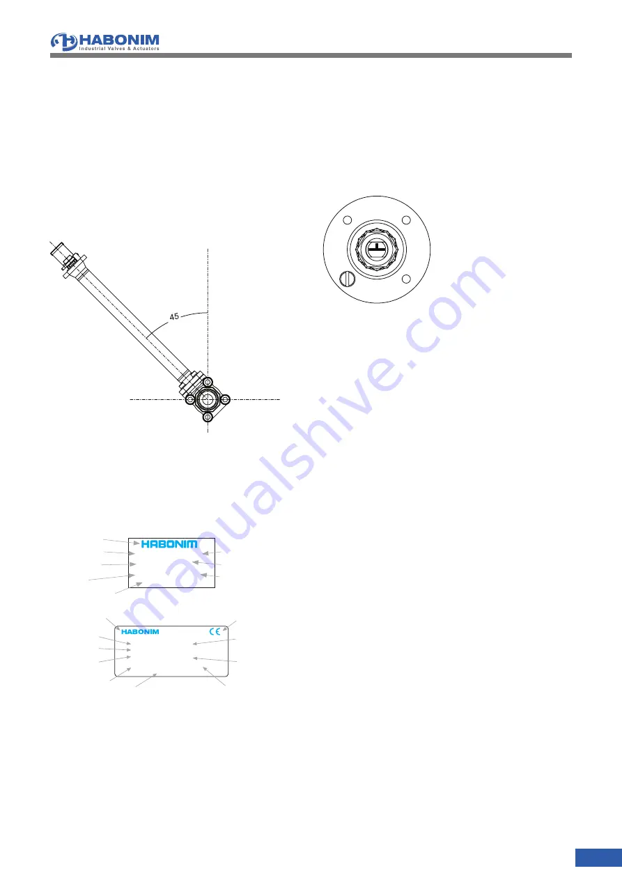
Habonim logo
Body material
Seat material
Valve size
Valve description
Ball material
Work order
Max. pressure
INDUSTRIAL VALVES & ACTUATORS LTD
KFAR HANASSI, 1230500 IL
BODY
BALL
SEAT
BAR @
°C
1155
Habonim logo
Body material
Max. pressure @
Min. temperature
Min. pressure @
Max. temperature
Valve description
CE mark
Ball material
Seat material
Valve size
Year manufacture
DN
P.O.
YR
BAR @
°C
once in 6 months for fully open/close position.
5.8.
Ball valves should be operated for at least two complete
cycles before installing or returning to storage.
6. INSTALLATION
Caution: DO NOT install Cryogenic valves with the extended
bonnet tilted more than 450 from the upright vertical position.
(see figure 1)
FIGURE 1
Valve Tilting Limitation
6.1 General
6.1.1.
Keep the valve in its polyethylene bag until ready for use.
Check the valve nameplate for identification of materials
(see Figure 2)
.
FIGURE
4.1.2.
When the valve is in the closed position the ball relief hole
will be seen in the upstream port of the valve as indicated
by the arrow. The stem head has an engraved "T" mark
identifying the ball port and the pressure relief hole direction
(See Figure 3)
.
FIGURE 3
Valve Top View
4.1.4.
When the valve is in the closed position the ball relief hole will
be seen in the upstream port of the valve as indicated by the
arrow. The stem head has an engraved "T" mark identifying
the ball port and the pressure relief hole direction
(See
Figure 3)
.Inspect the valve interior through the end ports to
determine that it is clean and free from foreign matter.
6.1.5.
Cycle the valve and inspect any functionally significant
features.
6.1.6.
Read all the literature, and note any special warning tags or
plates attached to the valve.
6.1.7.
During installation, it is recommended that the valve ball be left
in the open position to prevent possible damage to the ball.
6.2 Threaded End Valves
6.2.1.
Valves with screwed ends should be treated as a single unit
and should not be dismantled when installing to the pipeline.
6.2.2.
Before installing the valve, make sure that the threads on the
mating pipe are free from excessive grit, dirt or burrs.
6.2.3.
When tightening the valve, apply a pipe wrench or spanner
to the end connector closest to the pipe being worked, using
standard piping practices.
6.2.4.
Use appropriate joint sealing materials in correct quantities.
6.2.5.
If "back-welding" is required on screwed valves, refer to the
instructions for Weld End valves or to the "Habonim Welding
Instructions" bulletin.
6.3 In-line welding
6.3.1.
Cryogenic valves suitable for in-line welding are designed
with extended ends. Habonim ends identification code XBW,
ETO. (Socket welding is not recomended for Cryogenic use)
6.3.2.
Welding of valves shall be performed by a qualified welder
according to the ASME Boiler Construction Code Section
IX. For valves to be welded within the EEA, refer to the
requirements of ESR 3.1.2 of the Pressure Equipment
Directive 97/23/EC.
6.3.3.
Valves must be in the fully open position to protect the ball
and seats from excessive temperatures during the welding
procedures.
6.3.4.
Automated Valves in the "Fail Close" position should be


