1. Disconnect rear Z axis cover from column to allow access to the Z axis linear guides. Stone the two
column blocking bosses behind the column and place a 1-2-3 block on each. Place a bubble level on
the blocks and level the base, checking off of both Z axis linear guides with the level parallel to Z axis.
2. Place the level on the center of the table, parallel to the Z-axis, and note the position of the bubble.
3. Jog the table to the left, until the level is above screw 1, and note the position of the bubble.
4. Jog the table to the right, until the level is above screw 2, and note the position of the bubble.
5. Adjust for roll, by using screws 1 and 3 or screws 2 and 4 until the position of the bubble remains
constant over the full range of travel.
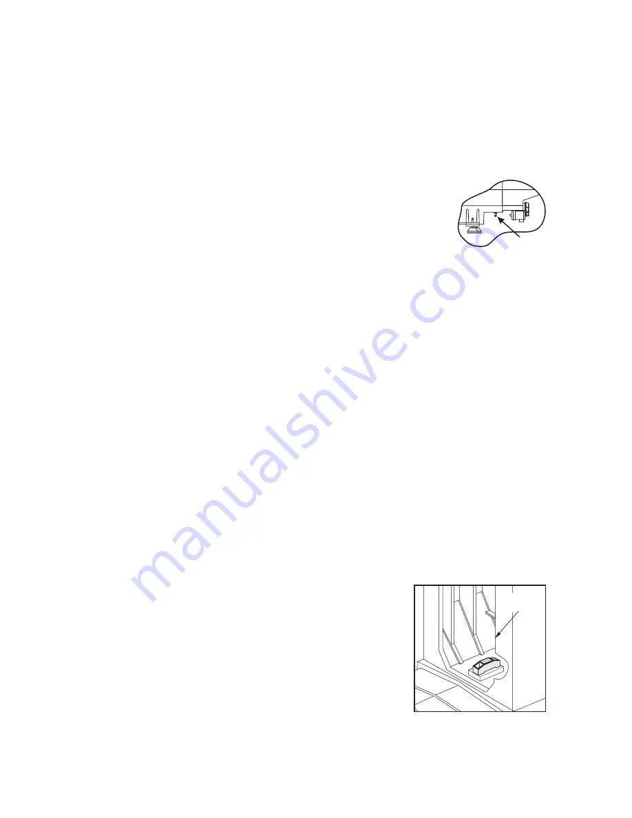
6. On newer EC-1600/2000 machines, X-axis pitch can be removed by adjusting the
jacking screws under the base (one on each side - see illustration). Readjust-
ment may be needed after heavy loads are placed on the table. For the EC-3000,
use the outrigger screws for pitch adjustment by turning the screws for each
outrigger by equal amounts in the same direction so as not to affect roll.
Note:
This adjustment is critical to the proper function of the machine. Pitch
and roll must be completely eliminated.
7. Jog the table to the center of travel.
8. Place 1-2-3 blocks (gauge blocks) on the platter or table, for machines without the A-axis platter,
(ensuring both surfaces are clean); one at the rear of the platter or inside of the table, and one at the
front of the platter, or outside edge of the table.
9. Attach a .0005" indicator to the spindle head and zero out on the block at the rear.
10. Jog the Z-axis to the front of the platter, or outside edge of the table, and indicate the 1-2-3 block at that
position.
11. Raise or lower screws 1 and 2 equally, and repeat, until readings between blocks without rotating the A-
axis platter are within .0001".
12. Remove roll from the Z-axis. Place a level on a 6" square of granite, or suitable block, inside the rear of
the column, with the level parallel to the X-axis. Shim the level as necessary. The level does not need to
be centered, just within a readable range.
13. Jog the column to the maximum (Z-negative) position and note the position of the bubble, then jog the
column to the maximum (Z-positive) position and note the position of the bubble. Adjust screws 7 and 8
by equal mounts in opposite directions, to eliminate roll without affecting the results of Steps 6
through 10.
14. Re-verify steps 2 through 11.
It is absolutely critical that these steps are correct before proceeding.
15. Adjust until readings at each end of the travel are within .0001".
16. Remove the level and the block from the back of the column.
17. Repeat Steps 6 through 10 to verify the Z-axis geometry in relation to the platter or table. Keep in mind
that when repeating these steps, that Z-axis roll has already been re-
moved, so leveling screws 7 and 8 must be adjusted up or down equally;
that is, both up or both down in equal amounts.
18. Remove pitch from the Z-axis. With a level placed parallel to the Z-axis
(inside the column), jog the column to the maximum (Z-negative) position
and note the position of the bubble, then jog the column to the maximum
(Z-positive) position and note the position of the bubble.
19. If necessary, adjust leveling screws 5, 6, 7 and 8 to correct for Z-axis
pitch.
Column
(Back Side)
Jack Screw
© Copyright 2015 by Haas Automation, Inc. No unauthorized reproduction.
Page 2 of 6


