background image

Maintenance

work

GB

9

4.2.2. Horizontal cleaning of the conduits of combustion products

• Get the cleaning bar from the rear cover of the stove. Next, remove the cover plug and dismount the screw

M10x70 by means of an Allen wrench, located behind the ash-pan door. After having finished the cleaning
by means of the blade, mount the screw and fit the cover plug to their places again. (see Fig. 3a-3c).

Summary of Contents for 0553708040000

Page 1: ...HSP 6 537 08 WT RLU PGI Equipment sheet Pellet stove with heat exchanger GB 0553708001403b Equipment sheet HSP 6 537 08 WT RLU PGI ...

Page 2: ...the heating device or of an injury The note entitled Notice advises you on possible damage to your heating device The note entitled Important calls your attention to the information important for the operation of your heating device The note itself calls your attention to the information important for the operation of your heating device in general ...

Page 3: ...ntenance work 6 4 1 Cleaning of the ash pan once a week 6 4 2 Cleaning of the exchanger once a week 8 4 2 1 Vertical cleaning of the exchanger 8 4 2 2 Horizontal cleaning of the conduits of combustion products 9 4 3 Cleaning of the exchanger 13 4 4 Cleaning the pellet container annual maintenance 16 5 Replacement parts list 17 5 1 Replacement parts list HSP 6 537 08 WT RLU PGI without trim parts 1...

Page 4: ......

Page 5: ...f storage container pellet tank about 32 kg Duration of burn with one charge min max about 15 h 60 h Permitted fuel Low dust wood pellets diameter 6 mm to Ö Norm M 7135 DIN plus EN plus A1 length max 30 mm Room heating capacity to DIN 18893 constant heating 340m 220m 130m Room heating capacity to DIN 18893 timed heating 225m 132m 90m Electricity supply 230 V 50 Hz Electricity supply input in norma...

Page 6: ...Dimensions GB 2 2 Dimensions 2 1 Dimensions ...

Page 7: ...onnection of the exchanger Item Name A Heating water output outside thread G3 4 B Return water intake outside thread G3 4 C Outlet of the safety valve outside thread G1 2 D Filling of the circulation system E Venting valve ...

Page 8: ...ustion chamber function instruction Error F040 The whole combustion space must be cleaned after 30 hours operation at the latest or once a week The requirement to clean the fire box flickering of the display appears during heating in case that the cleaning interval has elapsed After the fire box has been cleaned the error message Clean the fire box will be confirmed automatically The condition for...

Page 9: ...ering in the pellet tank might possibly result This will destroy your device and is not covered in your guarantee WARNING Cleaning the combustion pot may only be done with a cooled down stove in OFF operating mode Otherwise there is a risk of burns Take out the burner bowl from the stove Remove the remains of ashes and slag After the cleaning mount the burner bowl back to its proper position on th...

Page 10: ...ifications must not be operated Failure to observe this point will invalidate all guarantee claims 4 1 Cleaning of the ash pan once a week WARNING The frequency of maintenance in turn depends to a large extent on the pellet quality ash content Quality pellets have a low ash content of about 0 2 0 3 However if the ash content is higher 0 5 and over the interval from maintenance to maintenance is re...

Page 11: ...Maintenance work GB 7 Figure 1 ...

Page 12: ...u to clean the conduits of combustion products and the exchanger once in a week Please perform the short time cleaning in two steps 4 2 1 Vertical cleaning of the exchanger For the purposes of vertical cleaning move the cleaning lever 5 times at least in compliance with the Fig 2 Figure 2 ...

Page 13: ... cleaning bar from the rear cover of the stove Next remove the cover plug and dismount the screw M10x70 by means of an Allen wrench located behind the ash pan door After having finished the cleaning by means of the blade mount the screw and fit the cover plug to their places again see Fig 3a 3c ...

Page 14: ...Maintenance work GB 10 Figure 3a ...

Page 15: ...Maintenance work GB 11 Figure 3b ...

Page 16: ...nce work GB 12 Figure 3c Pos Description Piece No PR 1 Cover plug 1 piece 0553808006180 2 Allen wrench 6mm 1 piece 9001700060005 3 Screw M10x70 1 piece 0030121000705 4 Drawbar of cleaning 1 piece 0433317006063 ...

Page 17: ...as ducts at the latest after 1000 kg of pellets have been consumed Clean with a brush or an ash extractor CAUTION After completion of the cleaning make sure that when putting back the covers the seals are seated in the right positions It is essential to replace defective seals Please perform the long time cleaning in two steps ...

Page 18: ...Maintenance work GB 14 Figure 4 ...

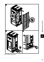
Page 19: ...Maintenance work GB 15 Figure 5 Removing the side wall ...

Page 20: ...e 1 in the pellet tank may be removed Then clean the tank and the intake of the screw conveyor housing with a vacuum cleaner After cleaning it is essential to put back the protective grille When doing this make sure that no screws fall into the pellet tank so as to avoid consequential damage to the screw conveyor Figure 6 Pellet tank 1 Protective grille 2 Tank cover ...

Page 21: ...Replacement parts list GB 17 5 Replacement parts list 5 1 Replacement parts list HSP 6 537 08 WT RLU PGI without trim parts ...

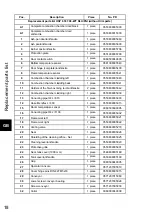
Page 22: ...le ri anthracite 2 piece 0553808005042 12 Combustion chamber cladding right 1 piece 0553808005039 13 Conecting pipe 3 4 L 670 1 piece 0553808005903 14 Hose Meniflex L 300 1 piece 0553808005315 15 Room temperature sensor 1 piece 0089500390005 16 Conecting pipe 3 4 L 1100 1 piece 0553808005902 17 Framework left 1 piece 0553808005021 18 Framework right 1 piece 0553808005022 19 Venting valve 1 piece 0...

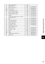
Page 23: ...05202 40 Outlets of the hydraulic system cock Ms Cross inserts set 1 piece 0088600000055 41 OC 2 piece 0089500080005 42 Flue gas thermosensor 1 piece 0561008005540 43 Conecting pipe L 550 1 piece 0553808005904 44 Induced draught fan 1 piece 0553808005808 45 Complete control unit 1 piece 0553808005569 46 Backup battery CR 2032 1 piece 47 Seal 191x136x4 1 piece 0553808005805 48 Tank cover screw 1 pi...

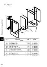
Page 24: ...acite set 1 piece 0553808005340 A1 3 Glass holder black set 1 piece 0551908035308 A1 3 Glass holder anthracite set 1 piece 0551908005308 52 Combustion chamber door black 1 piece 0541908007220 52 Combustion chamber door anthracite 1 piece 0541908005220 53 Seal glass 10x4 mm 900 mm 1 piece 0040210040005 54 Door glass 383x224x4 1 piece 0551908005305 55 Seal door 11 mm 1306 mm 1 piece 0040300110006 ...

Page 25: ... piece 0553808006140 56 58 Side wall left right white 2 piece 0553808016140 57 Front plate anthracite 1 piece 0553808016120 57 Front plate anthracite black 1 piece 0553808006120 59 Cover plate anthracite 1 piece 0553808017160 60 Back wall upper 1 piece 0553808006118 61 Back wall lower 1 piece 0553808006119 62 Edge cover 225 mm 1 piece 0089500640005 63 Hydraulik modul Set 1 piece 0553808114000 ...

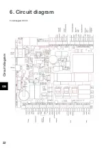
Page 26: ...Circuit diagram GB 22 6 Circuit diagram Circuit diagram IO 33 6 ...

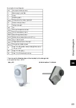
Page 27: ...37 38 Flame temperature sensor 39 40 Room temperature sensor 41 42 Bottom flame temperature sensor TFL 2 43 44 Door contact switch 46 47 Temperature sensor on the input 48 50 Flue gas fan rotation speed F1 Fuse T 3 15A ignition induced draught fan screw conveyor motor F2 Fuse T 3 15A pump F3 Fuse T 0 315A operator console You can use the following types of thermostats for the storage tank not supp...

Page 28: ......

Reviews: