background image

71 

Model Specifications 

HDD-Cage-8SFF-2U-3 

Front 8SFF SAS/SATA drive cage module for drive cage bay 3 

HDD-Cage-8SFF-2U-NVMe-2 

Front 8SFF NVMe drive cage module for drive cage bay 2 

HDD-Cage-8SFF-2U-2 

Front 8SFF SAS/SATA drive cage module for drive cage bay 2 

HDD-Cage-8SFF-2U-NVMe-1 

Front 8SFF NVMe drive cage module for drive cage bay 1 


Diagnostic panels 

Diagnostic panels provide diagnostics and troubleshooting capabilities. You can locate and 
troubleshoot component failures by using the diagnostic panels in conjunction with the event log 
generated in HDM. 


NOTE: 

A diagnostic panel displays only one component failure at a time. When multiple component failures 
exist, the diagnostic panel displays all these failures one by one at intervals of 4 seconds. 


Diagnostic panel specifications 

Model Specifications 

SD-SFF-A 

SFF diagnostic panel for the 25SFF server 

SD-SFF-B 

SFF diagnostic panel for the 8SFF server 

SD-LFF-G3-A 

LFF diagnostic panel for the LFF servers 


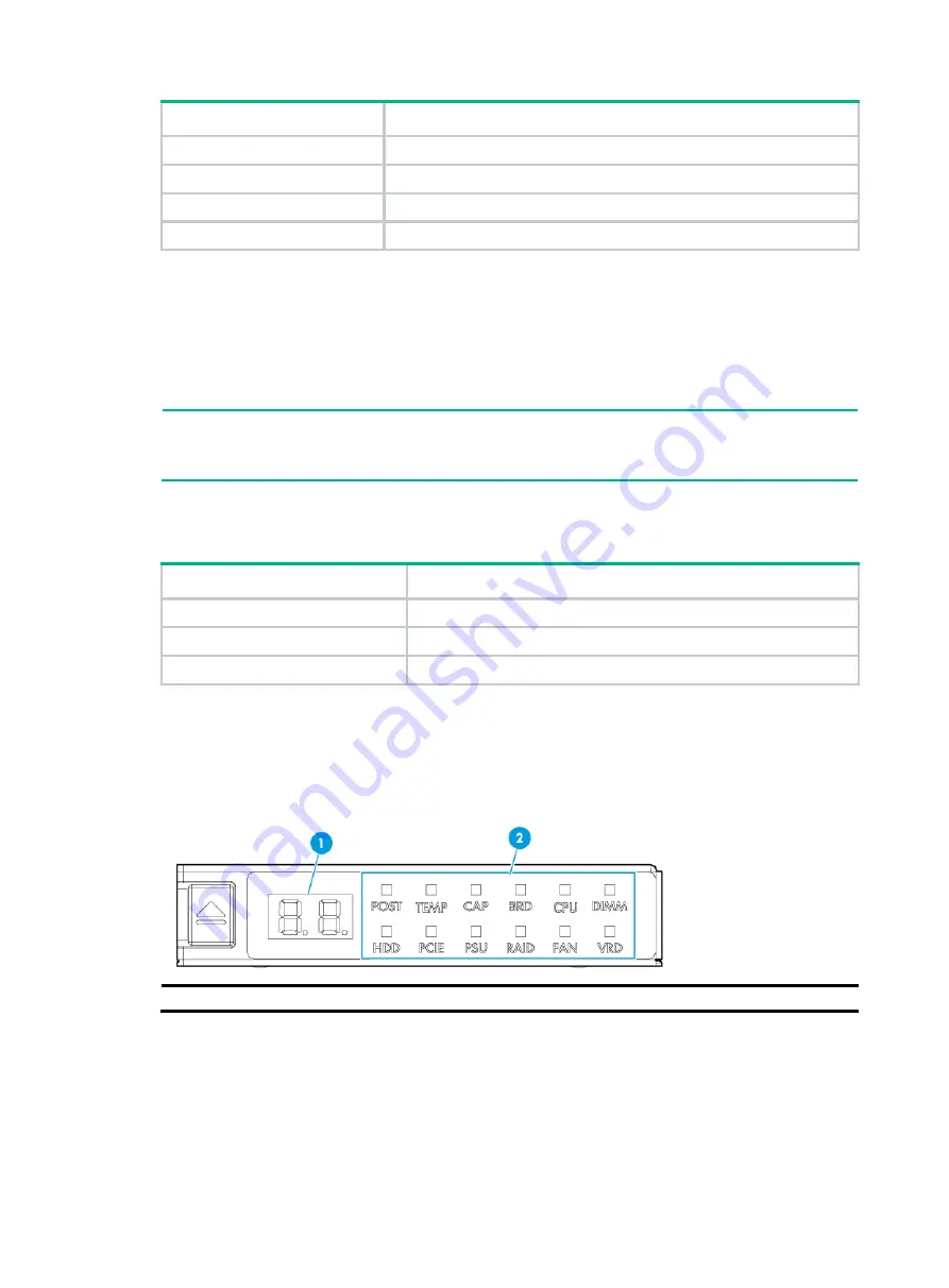
Diagnostic panel view 

Figure 43

 shows the error code and LEDs on a diagnostic panel.  

Figure 43 Diagnostic panel view 


(1) Error code 

(2) LEDs 


For more information about the LEDs and error codes, see "

LEDs

."


Summary of Contents for UniServer R4900 G3

Page 1: ...H3C UniServer R4900 G3 Server User Guide New H3C Technologies Co Ltd http www h3c com Document version 6W102 20190823...

Page 2: ...respective owners Notice The information in this document is subject to change without notice All contents in this document including statements information and recommendations are believed to be acc...

Page 3: ...equired syntax choices separated by vertical bars from which you select one x y Square brackets enclose a set of optional syntax choices separated by vertical bars from which you select one or none x...

Page 4: ...switch such as a Layer 2 or Layer 3 switch or a router that supports Layer 2 forwarding and other Layer 2 features Represents an access controller a unified wired WLAN module or the access controller...

Page 5: ...Documentation feedback You can e mail your comments about product documentation to info h3c com We appreciate your comments...

Page 6: ...the server 10 Optional Installing cable management brackets 11 Connecting external cables 11 Cabling guidelines 11 Connecting a mouse keyboard and monitor 11 Connecting an Ethernet cable 13 Connectin...

Page 7: ...with a power cord GPU dedicated chassis air baffle 59 Installing Ethernet adapters 61 Guidelines 61 Installing an mLOM Ethernet adapter 61 Installing a PCIe Ethernet adapter 62 Installing SATA M 2 SSD...

Page 8: ...placing a M 2 transfer module and a SATA M 2 SSD 122 Replacing the front M 2 transfer module and a SATA M 2 SSD 122 Replacing the rear M 2 transfer module and a SATA M 2 SSD 123 Replacing an SD card 1...

Page 9: ...ng the NCSI cable for a PCIe Ethernet adapter 189 Connecting the SATA M 2 SSD cable 190 Connecting the front SATA M 2 SSD cable 190 Connecting the rear SATA M 2 SSD cable 191 Connecting the SATA optic...

Page 10: ...any circumstances The surface or component might be hot and present burn hazards WARNING To avoid being burnt allow hot surfaces or components to cool before touching them The server or component is...

Page 11: ...ys use the power cords that came with the server Do not use the power cords that came with the server for any other devices Power off the server when installing or removing any components that are not...

Page 12: ...s including wearing antistatic clothing static dissipative shoes and antistatic gloves Use conductive field service tools Use a portable field service kit with a folding static dissipating work mat Co...

Page 13: ...he battery to a temperature higher than 60 C 140 F Do not disassemble crush puncture short external contacts or dispose of the battery in fire or water Dispose of the battery at a designated facility...

Page 14: ...r installation limits for different rack depth see Table 2 Table 2 Installation limits for different rack depths Rack depth Installation limits 1000 mm 39 37 in The H3C cable management arm CMA is not...

Page 15: ...7 80 in between the front rack posts and the CMA 6 860 mm 33 86 in between the front rack posts and the rear ends of the slide rails Installation site requirements Space and airflow requirements For c...

Page 16: ...nliness requirements Mechanically active substances buildup on the chassis might result in electrostatic adsorption which causes poor contact of metal components and contact points In the worst case e...

Page 17: ...ion T25 Torx screwdriver For captive screws inside chassis ears T30 Torx screwdriver For captive screws on processor heatsinks T15 Torx screwdriver shipped with the server For screws on access panels...

Page 18: ...SD prevention when you operate the server Antistatic clothing For ESD prevention when you operate the server Ladder For high place operations Interface cable such as an Ethernet cable or optical fiber...

Page 19: ...hipped with the rails Rack mounting the server WARNING To avoid bodily injury slide the server into the rack with caution for the sliding rails might squeeze your fingers 1 Slide the server into the r...

Page 20: ...on make sure no cables block the inlet or outlet air vents of the server To easily identify ports and connect disconnect cables make sure the cables do not cross Label the cables for easy identificati...

Page 21: ...rews on the plug Figure 5 Connecting a VGA cable 2 Connect the other plug of the VGA cable to the VGA connector on the monitor and fasten the screws on the plug 3 Connect the mouse and keyboard For a...

Page 22: ...r For the position of the HDM network port see Rear panel view 2 Determine the type of the Ethernet cable Verify the connectivity of the cable by using a link tester If you are replacing the Ethernet...

Page 23: ...USB 3 0 connector on the front panel if an installed chassis ear contains a VGA connector a USB 2 0 connector and a USB 3 0 connector Two USB 3 0 connectors on the rear panel Two internal USB 2 0 conn...

Page 24: ...If the server still fails to identify the USB device after the driver is installed replace the USB device Connecting the power cord Guidelines WARNING To avoid damage to the equipment or even bodily...

Page 25: ...of the power cord a Optional If the cable clamp is positioned too near the power cord that it blocks the power cord plug connection press down the tab on the cable mount and slide the clip backward Fi...

Page 26: ...clamp forward Connecting the DC power cord for a 48 VDC power supply WARNING Provide a circuit breaker for each power cord Make sure the circuit breaker is switched off before you connect a DC power...

Page 27: ...the DC power cord 3 Connect the other end of the power cord to the power source as shown in Figure 15 The DC power cord contains three wires 48V GND 48V and PGND Connect the three wires to the corresp...

Page 28: ...s positioning will enable the slide rails to slide easily in and out of the rack To secure cables to slide rails by using cable straps 1 Hold the cables against a slide rail 2 Wrap the strap around th...

Page 29: ...20 Figure 17 Extending the server from the rack 4 Place the server on a clean stable surface...

Page 30: ...the position of the system power LED see LEDs and buttons Powering on the server from the HDM Web interface 1 Log in to the HDM For information about how to log in to HDM see the firmware update guid...

Page 31: ...TANT This method forces the server to enter standby mode without properly exiting applications and the operating system Use this method only when the server system crashes For example a process gets s...

Page 32: ...uration flowchart Figure 18 Configuration flowchart Powering on the server 1 Power on the server For information about the procedures see Powering on the server 2 Verify that the health LED on the fro...

Page 33: ...user guide for the server Installing the operating system and hardware drivers Installing the operating system Install a compatible operating system on the server by following the procedures describe...

Page 34: ...25 You can update the following firmware from FIST or HDM HDM BIOS CPLD For information about the update procedures see the firmware update guide for the server...

Page 35: ...bezel as shown by callout 4 in Figure 19 Then pull out the key and keep it safe CAUTION To avoid damage to the lock hold down the key while you are turning the key Figure 19 Installing the security b...

Page 36: ...Remove the security bezel if any For more information see Replacing the security bezel 2 Press the latch on the drive blank inward with one hand and pull the drive blank out of the slot as shown in F...

Page 37: ...ive can be hot inserted at a time To hot insert multiple NVMe drives wait a minimum of 60 seconds for the previously installed NVMe drive to be identified before hot inserting another NVMe drive If yo...

Page 38: ...lever until it snaps into place Figure 25 Installing a drive 4 Optional Install the security bezel For more information see Installing the security bezel Verifying the installation Use the following m...

Page 39: ...heck and generate an alarm if the power supply models are different To avoid hardware damage do not use third party power supplies Procedure 1 As shown in Figure 26 remove the power supply blank from...

Page 40: ...odule does not exceed 75 W If the maximum power consumption exceeds 75 W a power cord is required The following GPU modules require a power cord GPU M4000 1 X GPU K80 1 GPU M60 1 X GPU P40 X GPU M10 X...

Page 41: ...nd a PCIe module The installation procedure is the same for the RC 3GPU R4900 G3 RC FHHL 2U G3 1 and RS 3 FHHL R4900 This section installs the RS 3 FHHL R4900 To install an RS 3 FHHL R4900 riser card...

Page 42: ...l the blank out of the slot as shown in Figure 29 Figure 29 Removing the PCIe module blank b Insert the PCIe module into the slot along the guide rails and use the screw to secure it into place as sho...

Page 43: ...ng on the server Installing an RC GPU FHHL 2U G3 1 riser card and a PCIe module 1 Power off the server For more information see Powering off the server 2 Remove the server from the rack For more infor...

Page 44: ...nk out of the slot as shown in Figure 33 Figure 33 Removing the PCIe module blank b Insert the PCIe module into the slot along the guide rails and use the screw to secure it into place as shown in Fig...

Page 45: ...RC 2 FHFL 2U G3 riser card can only be installed on PCIe riser connector 1 To install an RC 2 FHFL 2U G3 riser card and a PCIe module 1 Power off the server For more information see Powering off the...

Page 46: ...nect two PCIe signal cables to the RC Mezz Riser G3 Mezz PCIe riser card as shown in Figure 37 Figure 37 Connecting PCIe signal cables to the RC Mezz Riser G3 Mezz PCIe riser card 6 Lift the riser car...

Page 47: ...get PCIe slot and then pull the blank out of the slot as shown in Figure 39 Figure 39 Removing the PCIe module blank b Insert the PCIe module into the slot along the guide rails and use the screw to s...

Page 48: ...ack mount the server For more information see Rack mounting the server 13 Connect the power cord For more information see Connecting the power cord 14 Power on the server For more information see Powe...

Page 49: ...d then pull the blank out of the slot as shown in Figure 43 Figure 43 Removing the PCIe module blank b Insert the PCIe module into the slot along the guide rails and use the screw to secure it into pl...

Page 50: ...For more information see Rack mounting the server 11 Connect the power cord For more information see Connecting the power cord 12 Power on the server For more information see Powering on the server In...

Page 51: ...e blank in the target PCIe slot and then pull the blank out of the slot as shown in Figure 47 Figure 47 Removing the PCIe module blank b Insert the PCIe module into the slot along the guide rails and...

Page 52: ...e riser card blank 10 Install the power supply air baffle For more information see Installing air baffles 11 Connect PCIe module cables if any 12 Install the access panel For more information see Repl...

Page 53: ...nel 4 Remove the PCIe riser card blank from PCIe riser connector 3 as shown in Figure 42 5 Install the PCIe module to the riser card a Remove the screw on the PCIe module blank in the target PCIe slot...

Page 54: ...controller transfers data from DDR memory to the flash card where the data remains indefinitely or until the controller retrieves the data Guidelines To install two storage controllers make sure they...

Page 55: ...a power fail safeguard module Procedure 1 Power off the server For more information see Powering off the server 2 Remove the server from the rack For more information see Removing the server from a r...

Page 56: ...built in flash card For information about storage controllers with a built in flash card see Storage controllers a Install the two internal threaded studs supplied with the power fail safeguard module...

Page 57: ...Ie riser connector 1 and 2 For more information see Installing riser cards and PCIe modules 13 Install the removed fan cage For more information see Installing fans 14 Install the removed air baffles...

Page 58: ...torage controller IMPORTANT Skip this step if no power fail safeguard module is required or the storage controller has a built in flash card For information about storage controllers with a built in f...

Page 59: ...he power fail safeguard module 11 Connect the drive data cables to the standard storage controller For more information see 8SFF server 12 Install the removed fan cage For more information see Install...

Page 60: ...e 63 On the standard chassis air baffle BAT PMC G3 N A In the supercapacitor container BAT LSI G3 Only 8SFF server supports supercapacitor containers The location of the supercapacitor container is th...

Page 61: ...or Installing the supercapacitor on the air baffle The methods for installing a supercapacitor on the air baffle and in the server chassis are similar except that no supercapacitor holder is required...

Page 62: ...ving the drive or diagnostic panel you must also remove the 1SFF cage For information about removing a drive see Replacing a SAS SATA drive For information about removing a blank or serial label pull...

Page 63: ...ercapacitor Installing GPU modules Guidelines A riser card is required when you install a GPU module The available GPU modules and installation positions vary by riser card model and position For more...

Page 64: ...GPU module without a power cord standard chassis air baffle To install a GPU M4 1 GPU P4 X GPU T4 or GPU MLU100 D3 make sure all the six fans are present before you power on the server The procedure...

Page 65: ...CIe slot 2 along the guide rails and fasten the screw to secure the module into place as shown in Figure 69 Figure 69 Installing a GPU module 7 Install the riser card on PCIe riser connector 1 and the...

Page 66: ...or installing a GPU module in riser cards on PCIe riser connectors 1 2 and 3 This section uses the GPU M4000 1 X and PCIe riser connector 1 as an example Procedure 1 Determine the installation positio...

Page 67: ...w to secure the GPU module into place as shown by callouts 3 and 4 Figure 72 Installing a GPU module 9 Install the riser card on PCIe riser connector 1 and then fasten the captive screw to the chassis...

Page 68: ...ee Powering off the server 3 Remove the server from the rack For more information see Removing the server from a rack 4 Remove the access panel For more information see Replacing the access panel 5 Re...

Page 69: ...Remove the PCIe riser card blank from PCIe riser connector 1 as shown in Figure 28 b Align the installation hole on the GPU support bracket with the guide pin on the GPU dedicated chassis air baffle...

Page 70: ...ult port 1 on the mLOM Ethernet adapter acts as the HDM shared network port If only a PCIe Ethernet adapter exists and the PCIe Ethernet adapter supports NCSI port 1 on the PCIe Ethernet adapter acts...

Page 71: ...ing a PCIe Ethernet adapter Procedure 1 Power off the server For more information see Powering off the server 2 Remove the server from the rack For more information see Removing the server from a rack...

Page 72: ...Installing SATA M 2 SSDs at the server front Guidelines SATA M 2 SSDs and the SATA optical drive have the same installation location You can install only one of them If you are installing two SATA M...

Page 73: ...r of the SSD into the socket and push down the other end of the SSD Then fasten the screw provided with the transfer module to secure the SSD into place as shown in Figure 78 Figure 78 Installing a SA...

Page 74: ...power cord 17 Power on the server For more information see Powering on the server Installing SATA M 2 SSDs at the server rear Guidelines You can install a maximum of two SATA M 2 SSDs on an M 2 SSD e...

Page 75: ...rver For more information see Powering on the server Installing SD cards Guidelines The SD cards are hot swappable To achieve 1 1 redundancy and avoid storage space waste install two SD cards with the...

Page 76: ...card extended module 7 Optional Install the removed riser card on PCIe riser connector 3 For more information see Installing riser cards and PCIe modules 8 Install the access panel For more informatio...

Page 77: ...ur NVMe data cables to the NVMe SSD expander module as shown in Figure 83 Figure 83 Connecting an NVMe data cable to the NVMe SSD expander module 7 Install the NVMe SSD expander module to the server b...

Page 78: ...panel For more information see Replacing the access panel 9 Rack mount the server For more information see Rack mounting the server 10 Connect the power cord For more information see Connecting the p...

Page 79: ...Aligning the clip at the cage side with the edge of the riser card bracket place the drive cage in the chassis as shown by callout 1 in Figure 85 b Use screws to secure the drive cage as shown in Figu...

Page 80: ...For more information see Replacing the access panel 4 Remove the chassis air baffle For more information see Removing air baffles 5 Remove the fan cage For more information see Replacing the fan cage...

Page 81: ...e For more information see Replacing the fan cage 6 Remove the blank for PCIe riser connector 2 as shown in Figure 32 7 Place the rear 2LFF drive cage in the chassis and use screws to secure it into p...

Page 82: ...cage 9 Connect AUX signal cable data cable and power cord to the rear 4LFF drive backplane For more information see Rear 4LFF SAS SATA drives 10 Install drives in the rear 4LFF drive cage For more inf...

Page 83: ...he drive cage into the server as shown in Figure 92 5 Install drives in the front 8SFF drive cage For more information see Installing SAS SATA drives 6 Paste the drive label on the server s front pane...

Page 84: ...6 Remove the security bezel if any For more information see Replacing the security bezel 7 Remove the screws that secure the drive cage bay blank over drive cage bay 1 and then push the blank from th...

Page 85: ...enablement option in drive cage bay 1 and fasten the screws to secure the option into place as shown in Figure 92 Figure 92 Installing the optical drive enablement option 10 Insert the SATA optical dr...

Page 86: ...d 18 Power on the server For more information see Powering on the server Installing a diagnostic panel Preparing for the installation For the installation location of the diagnostic panel see Front pa...

Page 87: ...ore information see Removing the server from a rack 3 Remove the access panel For more information see Replacing the access panel 4 Remove the chassis air baffle For more information see Removing air...

Page 88: ...e diagnostic panel as follows a Connect one end of the cable P N 0404A0SP to the front panel of the diagnostic panel and the other end to the transfer module of the diagnostic panel as shown in Figure...

Page 89: ...tion see Removing the server from a rack 3 Remove the access panel For more information see Replacing the access panel 4 Remove the chassis air baffle For more information see Removing air baffles 5 R...

Page 90: ...iagnostic panel a Connect the diagnostic panel cable P N 0404A0T1 to the diagnostic panel as shown in Figure 100 Figure 100 Connecting the diagnostic panel cable b Push the diagnostic panel into the s...

Page 91: ...rver For more information see Powering on the server Installing the SD LFF G3 A LFF diagnostic panel 1 Power off the server For more information see Powering off the server 2 Remove the server from th...

Page 92: ...formation about removing a drive see Replacing a SAS SATA drive 8 For an 8LFF or 12LFF server with the BP 12LFF R4900 drive backplane install the diagnostic panel as follows a Connect one end of the c...

Page 93: ...diagnostic panel as follows a Connect one end of the cable P N 0404A0SP to the front panel of the diagnostic panel and the other end to the transfer module of the diagnostic panel as shown in Figure 1...

Page 94: ...nt space is available for installation you can install the serial label pull tab module without powering off the server or removing the server from the rack The following procedure is provided based o...

Page 95: ...ame for the serial label pull tab module and the SFF diagnostic panel For more information see Installing the SD SFF B SFF diagnostic panel 6 Install the removed security bezel For more information se...

Page 96: ...n bays 3 through 6 and the remaining fan bays can be empty If a fan bay is empty make sure a fan blank is installed For the locations of fans in the server see Fans The fans support N 1 redundancy If...

Page 97: ...information see Replacing the access panel 6 Rack mount the server For more information see Installing the server 7 Connect the power cord For more information see Connecting the power cord 8 Power o...

Page 98: ...2 Power off the server For more information see Powering off the server 3 Remove the server from the rack For more information see Removing the server from a rack 4 Remove the access panel For more in...

Page 99: ...ning bracket onto the heatsink CAUTION When you remove the protective cover over the heatsink be careful not to touch the thermal grease on the heatsink a Lift the cover straight up until it is remove...

Page 100: ...gile Damage to pins will incur system board replacement Keep the pins on the processor socket clean Make sure the socket is free from dust and debris Hold the cover by the notches on its two edges and...

Page 101: ...lling the server 15 Connect the power cord For more information see Connecting the power cord 16 Power on the server For more information see Powering on the server Verifying the installation Log in t...

Page 102: ...memory mode setting to take effect make sure the following DIMM installation requirements are met when you install DRAM DIMMs for a processor Memory mode DIMM requirements Independent If only one proc...

Page 103: ...and DCPMM in a channel install the DRAM DIMM in the white slot and the DCPMM in the black slot To install only one DIMM in a channel install the DIMM in the white slot if the DIMM is DCPMM A6 A12 A5...

Page 104: ...DIMM slots numbering b Open the DIMM slot latches c Align the notch on the DIMM with the connector key in the DIMM slot and press the DIMM into the socket until the latches lock the DIMM in place as...

Page 105: ...ox and then click the msinfo32 item In the CLI of a Linux OS execute the cat proc meminfo command Log in to HDM For more information see HDM online help Access the BIOS For more information see the BI...

Page 106: ...take appropriate measures to ensure the integrity of the system data H3C is not liable for blocked data access caused by improper use of the TCM or TPM For more information see the encryption technolo...

Page 107: ...e TCM or TPM is operating correctly For more information see HDM online help Configuring encryption in the operating system For more information about this task see the encryption technology feature d...

Page 108: ...he server from the rack The following procedure is provided based on the assumption that no sufficient space is available for replacement Removing the access panel 1 Power off the server For more info...

Page 109: ...all the access panel as shown in Figure 125 a Place the access panel on top of the server chassis with the guide pin in the chassis aligned with the pin hole in the locking lever area as shown by call...

Page 110: ...126 Removing the security bezel 4 Install a new security bezel For more information see Installing the security bezel Replacing a SAS SATA drive The drives are hot swappable To configure RAID setting...

Page 111: ...troller user guide for the server Access the CLI or GUI of the server Observe the drive LEDs to verify that the drive is operating correctly For more information about drive LEDs see Drive LEDs Replac...

Page 112: ...out drive LEDs see Drive LEDs Replacing a power supply The power supplies are hot swappable If two power supplies are installed and sufficient space is available for replacement you can replace a powe...

Page 113: ...remove the DC power cord from a 48 VDC power supply a Loosen the captive screws on the power cord plug as shown in Figure 130 Figure 130 Loosening the captive screws b Pull the power cord plug out of...

Page 114: ...y in slot 2 7 Mount the server in the rack For more information see Installing the server 8 Connect the power cord For more information see Connecting the power cord 9 Power on the server For more inf...

Page 115: ...need to remove the GPU P100 GPU V100 or GPU V100 32G module For more information about removing a riser card and a GPU module see Replacing a riser card and a PCIe module and Replacing a GPU module 5...

Page 116: ...is edges as shown in Figure 135 The installation procedure is the same for the standard chassis air baffle and the GPU dedicated chassis air baffle The following figure uses the standard chassis air b...

Page 117: ...re information see Powering on the server Replacing a riser card and a PCIe module WARNING To avoid bodily injury from hot surfaces allow the server and its internal modules to cool before touching th...

Page 118: ...mation see Replacing the access panel 9 Mount the server in the rack For more information see Installing the server 10 Connect the power cord For more information see Connecting the power cord 11 Powe...

Page 119: ...igure 139 Disconnecting PCIe signal cables from the RC Mezz Riser G3 Mezz PCIe riser card 6 Loosen the captive screw on the module and pull the module out of the chassis as shown in Figure 140 Figure...

Page 120: ...replace the storage controller with a controller of the same model identify the following information before the replacement Storage controller location and cabling Storage controller model operating...

Page 121: ...r baffles 14 Install the access panel For more information see Replacing the access panel 15 Rack mount the server For more information see Rack mounting the server 16 Connect the power cord For more...

Page 122: ...Verifying the replacement Log in to HDM to verify that the standard storage controller is in a correct state For more information see HDM online help Replacing the power fail safeguard module WARNING...

Page 123: ...tor To remove the supercapacitor in the server chassis pull the clip on the supercapacitor holder take the supercapacitor out of the holder and then release the clip as shown in Figure 143 Then lift t...

Page 124: ...lder and then release the clip as shown in Figure 143 To remove the supercapacitor in the supercapacitor container remove the screw that secures the supercapacitor container and then pull the cage out...

Page 125: ...fying the replacement Log in to HDM to verify that the flash card and the supercapacitor are in a correct state For more information see HDM online help Replacing the power fail safeguard module for a...

Page 126: ...baffles 13 Install the access panel For more information see Replacing the access panel 14 Rack mount the server For more information see Rack mounting the server 15 Connect the power cord For more i...

Page 127: ...ower cord from the riser card as shown by callout 2 in Figure 149 c Pull the GPU module out of the PCIe slot and then remove the power cord of the GPU module if any as shown by callouts 3 and 4 in Fig...

Page 128: ...e a GPU module with a power cord and a GPU dedicated chassis air baffle 1 Power off the server For more information see Powering off the server 2 Remove the server from the rack For more information s...

Page 129: ...r more information see Powering on the server Verifying the installation Log in to HDM to verify that the GPU module is operating correctly For more information see HDM online help Replacing an Ethern...

Page 130: ...ormation see Powering off the server 2 Remove the server from the rack For more information see Removing the server from a rack 3 Remove the access panel For more information see Replacing the access...

Page 131: ...cess panel 4 Remove the chassis air baffle For more information see Removing air baffles 5 Remove the fan cage For more information see Replacing the fan cage 6 Remove the security bezel if any For mo...

Page 132: ...s panel 4 Disconnect the SATA M 2 SSD cable from the system board For more information see Connecting the SATA M 2 SSD cable 5 Remove the riser card that has a M 2 transfer module attached For more in...

Page 133: ...ver from the rack For more information see Removing the server from a rack 3 Remove the access panel For more information see Replacing the access panel 4 For the ease of replacement remove the PCIe r...

Page 134: ...the blue clip on the dual SD card extended module as shown by callout 1 in Figure 156 Pull the module out of the connector and then release the clip Figure 156 Removing the dual SD card extended modul...

Page 135: ...s b Remove the PCIe riser card that contains the NVMe SSD expander module For more information see Replacing a riser card and a PCIe module c Disconnect cables from the NVMe SSD expander modules as sh...

Page 136: ...baffles 5 Hold the ring part of the NVMe VROC module and pull the module out of the chassis as shown in Figure 158 Figure 158 Removing the NVMe VROC module 6 Install a new NVMe VROC module For more i...

Page 137: ...s panel 4 Pinch the latches on both sides of the fan to pull the fan out of the slot as shown in Figure 159 Figure 159 Removing a fan 5 Install a new fan For more information see Installing fans 6 Ins...

Page 138: ...nstalling air baffles 8 Install the access panel For more information see Replacing the access panel 9 Rack mount the server For more information see Rack mounting the server 10 Power on the server Fo...

Page 139: ...ollowing methods to verify that the memory size is correct Access the GUI or CLI of the server In the GUI of a windows OS click the Start icon in the bottom left corner enter msinfo32 in the search bo...

Page 140: ...om the rack For more information see Removing the server from a rack 3 Remove the access panel For more information see Replacing the access panel 4 Remove the chassis air baffle For more information...

Page 141: ...d pushing down and the other hand tilting the processor as shown in Figure 164 Figure 164 Separating the processor from the retaining bracket Installing a processor 1 Install the processor onto the re...

Page 142: ...processors 5 Past bar code label supplied with the processor over the original processor label on the heatsink IMPORTANT This step is required for you to obtain H3C s processor servicing 6 Optional R...

Page 143: ...erver Replacing the system battery WARNING To avoid bodily injury from hot surfaces allow the server and its internal modules to cool before touching them The server comes with a system battery Panaso...

Page 144: ...shown by callout 1 in Figure 169 2 Press the system battery to seat it in the holder as shown by callout 2 in Figure 169 Figure 169 Installing the system battery 3 Optional Install the removed PCIe m...

Page 145: ...e Replacing the access panel 5 Remove the air baffles For more information see Removing air baffles 6 Remove the fan cage For more information see Replacing the fan cage 7 Disconnect all cables connec...

Page 146: ...by its handle and slide the system board toward the server front Then lift the system board to remove it from the chassis as shown in callout 2 in Figure 171 Figure 171 Removing the system board Insta...

Page 147: ...ds and PCIe modules 9 Install the removed rear 2LFF or 4LFF drive cage For more information see Installing a front or rear drive cage 10 Connect cables to the system board 11 Install the fan cage For...

Page 148: ...ve the fan cage if it hinders the replacement For more information see Replacing the fan cage 6 Disconnect cables from the expander module 7 Loosen the captive screws that secure the expander module a...

Page 149: ...25SFF drive expander module 9 Connect cables to the drive expander module 10 Install the removed fan cage For more information see Replacing the fan cage 11 Install the removed chassis air baffle For...

Page 150: ...more information see Replacing the fan cage 6 Remove the security bezel if any For more information see Replacing the security bezel 7 Remove the drives attached to the backplane For more information...

Page 151: ...the rear 2SFF 4SFF 2LFF and 4LFF drive backplanes This procedure uses the rear 2SFF drive backplane Figure 177 Removing a rear 2SFF drive backplane Installing drive backplanes 1 Install drive backplan...

Page 152: ...plane 2 Connect cables to the drive backplanes For more information see Connecting drive cables 3 Install the removed drive expander module For more information see Replacing the drive expander module...

Page 153: ...e Removing the server from a rack 3 Remove the access panel For more information see Replacing the access panel 4 Remove the chassis air baffle For more information see Removing air baffles 5 Remove t...

Page 154: ...access panel 4 Remove the chassis air baffle if it hinders the replacement For more information see Removing air baffles 5 Remove the fan cage if it hinders the replacement For more information see R...

Page 155: ...ormation see Replacing the security bezel 4 Remove the serial label pull tab module The removal method is the same for the serial label pull tab module and the diagnostic panel For more information se...

Page 156: ...m module attached to the left chassis ear as an example 5 Remove the left chassis ear if the chassis open alarm module is attached to the left chassis ear For more information see Removing the left ch...

Page 157: ...re information see Powering on the server Replacing chassis ears WARNING To avoid bodily injury from hot surfaces allow the server and its internal modules to cool before touching them Replacing the r...

Page 158: ...oward the rear of the chassis and then remove it from the chassis as shown by callouts 1 and 2 in Figure 185 c Pull the I O component cable out of the slot as shown by callout 3 in Figure 185 Figure 1...

Page 159: ...the front I O component cable assembly into the cable cutout as shown by callout 1 in Figure 188 b Attach the cable protection plate to the chassis front of the server with its keyed slots over the pe...

Page 160: ...ng the fan cage 4 Install the chassis air baffle For more information see Installing air baffles 5 Install the access panel For more information see Replacing the access panel 6 Rack mount the server...

Page 161: ...t chassis ear Installing the left chassis ear 1 Install the left chassis ear The installation procedure is the same for the left and right chassis ears For more information see Installing the right ch...

Page 162: ...15 to select the method for connecting the 8SFF SAS SATA drive backplane to a storage controller depending on the type of the storage controller Table 15 8SFF SAS SATA drive cabling methods Storage c...

Page 163: ...controller 1 AUX signal cable 2 Power cord 3 SAS SATA data cable NOTE The cabling method is the same for standard storage controllers in PCIe slots 2 and 6 of riser cards This figure uses slot 6 as an...

Page 164: ...Mezzanine storage controller Connect drives in drive cage bay 3 to the standard storage controller in PCIe slot 6 Standard storage controller UN RAID LSI 9460 16i 4G See Figure 194 N A Figure 193 16SF...

Page 165: ...spectively to determine the ports to be connected and the cable to use Use Table 17 to determine the front drive cabling method depending on the type of storage controller and NVMe SSD expander module...

Page 166: ...expander module 1 AUX signal cables 2 and 3 Power cords 4 SATA data cable 5 NVMe data cables Figure 196 Hybrid 8SFF SAS SATA and 8SFF NVMe drive cabling embedded storage controller and 4 port NVMe SSD...

Page 167: ...expander modules 1 AUX signal cables 2 and 3 Power cords 4 SATA data cable 5 and 6 NVMe data cables Figure 198 Hybrid 8SFF SAS SATA and 8SFF NVMe drive cabling Mezzanine storage controller and 8 port...

Page 168: ...2 NVMe A2 NVMe 3 NVMe A3 NVMe A3 NVMe 4 NVMe A4 NVMe A4 NVMe 1 NVMe B1 NVMe B1 NVMe 2 NVMe B2 NVMe B2 NVMe 3 NVMe B3 NVMe B3 NVMe 4 NVMe B4 NVMe B4 Table 19 NVMe data cable and the corresponding peer...

Page 169: ...and 4 port NVMe SSD expander modules use Table 18 and Table 19 respectively to determine the ports to be connected and the cable to use Use Table 20 to determine the front drive cabling method dependi...

Page 170: ...e in PCIe slot 2 When connecting NVMe data cables make sure you connect the corresponding peer ports with the correct NVMe data cable For 8 port and 4 port NVMe SSD expander modules use Table 18 and T...

Page 171: ...Figure 203 8SFF NVMe drive cabling one 8 port NVMe SSD expander module 1 AUX signal cable 2 Power cord 3 NVMe data cables Front 16SFF NVMe drive cabling To install 16SFF NVMe drives you must install...

Page 172: ...t NVMe SSD expander modules in PCIe slots 2 and 5 Use Table 18 to determine the ports to be connected and the cable to use Use Table 22 to determine the front drive cabling method depending on the typ...

Page 173: ...ntroller 1 and 5 Power cords 2 and 4 AUX signal cables 3 SAS SATA data cable 6 and 7 NVMe data cables Figure 206 Hybrid 8SFF SAS SATA and 16SFF NVMe drive cabling Mezzanine storage controller 1 and 4...

Page 174: ...18 to determine the ports to be connected and the cable to use If the BP 24SFF NVMe R4900 G3 drive backplane is installed use Table 24 to determine the ports to be connected and the cable to use Use...

Page 175: ...the BP 24SFF NVMe R4900 G3 1 and 4 Power cords 2 and 3 AUX signal cables 5 to 7 NVMe data cables Figure 209 24SFF NVMe drive cabling drive backplane BP 24SFF NVMe R4900 G3 1 1 NVMe data cables P N 04...

Page 176: ...le Single port end for the drive backplane Dual port end for the NVMe SSD expander module 0404A121 NVMe A1 NVMe A1 NVMe A1 NVMe A1 NVMe A2 NVMe A2 NVMe A2 NVMe A2 NVMe A3 NVMe A3 NVMe A4 NVMe A4 NVMe...

Page 177: ...5SFF server Front 25SFF SAS SATA drive cabling with the BP 25SFF R4900 25SFF drive backplane Use Table 25 to select the method for connecting the drive backplane to a storage controller depending on t...

Page 178: ...ane Use Table 26 to select the method for connecting the drive backplane to a storage controller depending on the type of the storage controller Table 26 25SFF SAS SATA drive cabling methods Storage c...

Page 179: ...r the 25SFF server depending on the type of the drive backplane Table 27 Rear 2SFF SAS SATA drive cabling methods Drive backplane Cabling method Drive backplane without functions of a drive expander m...

Page 180: ...cord Rear 4SFF SAS SATA drive cabling Connect the rear 4SFF SAS SATA drive cables for the 25SFF server as shown in Figure 217 Figure 217 Rear 4SFF SAS SATA drive cabling for the 25SFF server 1 SAS SA...

Page 181: ...ble 28 to select the method for connecting the 8LFF drive backplane to a storage controller depending on the type of the storage controller Table 28 8LFF drive cabling methods Storage controller Cabli...

Page 182: ...e connected to the embedded RSTe RAID controller 1 AUX signal cable 2 Power cord 3 SATA data cable Figure 220 8LFF SAS SATA drive connected to the Mezzanine storage controller 1 AUX signal cable 2 Pow...

Page 183: ...figure uses slot 6 as an example 12LFF server Front 12LFF SAS SATA drive cabling with the BP 12LFF R4900 drive backplane Use Table 29 to select the method for connecting the 12LFF drive backplane to...

Page 184: ...ntroller 1 AUX signal cable 2 Power cord 1 3 SAS SATA data cable 4 Power cord 2 NOTE The cabling method is the same for standard storage controllers in PCIe slots 2 and 8 This figure uses slot 8 as an...

Page 185: ...methods Storage controller Cabling method Remarks Embedded RSTe RAID controller See Figure 224 Install the NVMe SSD expander module in PCIe slot 2 Mezzanine storage controller See Figure 225 Install t...

Page 186: ...SAS SATA and 4LFF NVMe drive cabling standard storage controller in PCIe slot 6 1 AUX signal cable 2 and 3 Power cords 4 SAS SATA data cable 5 NVMe data cables Table 31 NVMe data cable and the corresp...

Page 187: ...type of storage controller Table 32 Hybrid 8LFF SAS SATA and 4LFF SAS SATA NVMe drive cabling methods Storage controller Cabling method Description Standard storage controller RAID LSI 9460 16i 4G Se...

Page 188: ...data cables Hybrid front 8LFF SAS SATA front 4LFF SAS SATA NVMe drive and rear 2SFF SAS SATA drive cabling To use this drive configuration install a 4 port NVMe SSD expander module in PCIe slot 5 a s...

Page 189: ...ive backplane Use Table 29 to select the method for connecting the 12LFF drive backplane to a storage controller depending on the type of the storage controller Table 33 12LFF drive cabling methods St...

Page 190: ...es of the storage controllers Table 34 12LFF drive cabling methods Storage controller Cabling method Remarks Standard storage controllers See Figure 233 Connect front drives 0 through 7 to the standar...

Page 191: ...storage controller and standard storage controller in PCIe slot 6 1 and 7 AUX signal cables 2 3 and 6 Power cords 4 and 5 SAS SATA data cables Rear 2SFF SAS SATA drive cabling Use Table 35 to select t...

Page 192: ...2U G3 1 SAS SATA data cable 2 AUX signal cable 3 Power cord Figure 236 Rear 2SFF drive cabling for the 12LFF server BP2 12LFF 2U G3 drive backplane 1 AUX signal cable 2 data cable 3 Power cord Rear 4S...

Page 193: ...rect NVMe data cable Use Table 36 to determine the ports to be connected and the cable to use Figure 238 Rear 4SFF SAS SATA NVMe drive cabling for the 12LFF server 1 SAS SATA data cable 2 AUX signal c...

Page 194: ...TA NVMe drive cabling for the 12LFF server 1 SAS SATA data cable 2 AUX signal cable 3 Power cord 4 and 5 NVMe data cable Table 37 NVMe data cable and the corresponding peer ports on the drive backplan...

Page 195: ...2U G3 1 SAS SATA data cable 2 Power cord 3 AUX signal cable Figure 241 Rear 2LFF drive cabling for the 12LFF server BP2 12LFF 2U G drive backplane 1 AUX signal cable 2 SAS SATA data cable 3 Power cord...

Page 196: ...rd module The flash card of the power fail safeguard module can be installed on a Mezzanine storage controller or on a standard storage controller Choose the connection procedure depending on the loca...

Page 197: ...ller The cabling method is similar for standard storage controllers in any PCIe slots Figure 244 uses slot 1 to show the cabling method Figure 244 Connecting the flash card on a standard storage contr...

Page 198: ...re 245 Figure 245 Connecting the power cord of a GPU module Connecting the NCSI cable for a PCIe Ethernet adapter The cabling method is the same for standard storage controllers in any PCIe slots Figu...

Page 199: ...are installing two SATA M 2 SSDs connect the cable as shown in Figure 248 The front SATA M 2 SSD cable can transmit power to the drive backplane For a 16SFF SAS SATA drive configuration or an 8SFF SAS...

Page 200: ...TA M 2 SSD connect the cable as shown in Figure 249 If you are installing two SATA M 2 SSDs connect the cable as shown in Figure 250 Figure 249 Connecting the rear SATA M 2 SSD cable one SATA M 2 SSD...

Page 201: ...y The front I O component cable assembly is a two to one cable attached to the right chassis ear Connect the cable to the front I O component connector on the system board as shown in Figure 252 Figur...

Page 202: ...e 253 Connecting the cable for the front VGA and USB 2 0 connectors on the left chassis ear Connecting the diagnostic panel cable Two cabling methods for diagnostic panels are available as shown in Fi...

Page 203: ...194 Figure 255 Connecting the diagnostic panel cable 2...

Page 204: ...used prepare a new one Keep the network topology up to date to facilitate network troubleshooting Maintenance tools The following are major tools for server maintenance Hygrothermograph Monitor the o...

Page 205: ...nical support If you encounter any complicated problems during daily maintenance or troubleshooting contact H3C Support Before contacting H3C Support collect the following server information to facili...

Page 206: ...ns 17 Drive LEDs 26 Drive configurations and numbering 27 PCIe modules 38 Storage controllers 38 NVMe SSD expander modules 48 GPU modules 48 PCIe Ethernet adapters 54 FC HBAs 56 mLOM Ethernet adapters...

Page 207: ...Performing a managed hot removal from the CLI 77 Performing a managed hot removal from the Intel ASM Web interface 78 Appendix D Environment requirements 81 About environment requirements 81 General...

Page 208: ...r configuration see Drive configurations and numbering Table 1 R4900 G3 server models Model Maximum drive configuration 8SFF 24 SFF drives at the front 8LFF 8 LFF drives at the front 12LFF 12 LFF driv...

Page 209: ...ear and one at the server front 1 BIOS serial port at the server rear Expansion slots 10 PCIe 3 0 modules eight standard PCIe modules one Mezzanine storage controller and one Ethernet adapter Optical...

Page 210: ...ols the processor 6 Processor Integrates a memory processing unit and a PCIe controller to provide data processing capabilities for the server 7 System board One of the most important parts of a serve...

Page 211: ...ich is hot swappable 21 M 2 transfer module Expands the server with a maximum of two SATA M 2 SSDs 22 Optical drive Used for operating system installation and data backup 23 Drive expander module Prov...

Page 212: ...SATA drives or 8SFF NVMe SSDs optional 6 Diagnostic panel or serial label pull tab module optional 7 USB 3 0 connector Figure 4 25SFF front panel 1 VGA connector optional 2 USB 2 0 connector optional...

Page 213: ...Figure 7 shows the front panel LEDs and buttons Table 3 describes the status of the front panel LEDs Figure 7 Front panel LEDs and buttons 1 Health LED 2 mLOM Ethernet adapter Ethernet port LED 3 Pow...

Page 214: ...he UID LED can be activated by using the following methods Press the UID button LED Activate the UID LED from HDM Flashing blue 1 Hz The firmware is being upgraded or the system is being managed from...

Page 215: ...Ds Figure 9 shows the rear panel LEDs Table 5 describes the status of the rear panel LEDs Figure 9 Rear panel LEDs 1 Link LED of the Ethernet port 2 Activity LED of the Ethernet port 3 UID LED 4 Power...

Page 216: ...y has correct power input Flashing amber 1 Hz An alarm has occurred on the power supply Off No power supplies have power input which can be caused by an incorrect power cord connection or power source...

Page 217: ...ont I O connector 12 Optical SATA port 13 Diagnostic panel connector 14 Front drive backplane power connector 1 15 Dual internal USB 3 0 connector 16 Front drive backplane AUX connector 2 or rear driv...

Page 218: ...passwords from the BIOS jump pins 2 and 3 and then start the server All the passwords will be cleared from the BIOS Before the next server startup jump pins 1 and 2 to perform a normal server startup...

Page 219: ...12 Figure 11 DIMM physical layout...

Page 220: ...ble 9 Skylake processors Model Base frequency Power Number of cores Cache L3 UPI links UPI speed Supported max data rate of DIMMs 8180 2 5 GHz 205 W 28 38 50 MB 3 10 4 GT s 2666 MHz 8176 2 1 GHz 165 W...

Page 221: ...s 2400 MHz 4114 2 2 GHz 85 W 10 13 75 MB 2 9 6 GT s 2400 MHz 4112 2 6 GHz 85 W 4 8 25 MB 2 9 6 GT s 2400 MHz 4110 2 1 GHz 85 W 8 11 MB 2 9 6 GT s 2400 MHz 4108 1 8 GHz 85 W 8 11 MB 2 9 6 GT s 2400 MHz...

Page 222: ...24 75 MB 3 10 4 GT s 2933 6230 2 1 GHz 125 W 20 27 5 MB 3 10 4 GT s 2933 5220 2 2 GHz 125 W 18 24 75 MB 2 10 4 GT s 2666 5218 2 3 GHz 125 W 16 22 MB 2 10 4 GT s 2666 6240Y 2 6 GHz 150 W 18 24 75 MB 3...

Page 223: ...l rank 0231AAEJ DDR4 2666 32G 2Rx4 R 2 RDIMM 32 GB 2666 MHz Dual rank 0231AAEK DDR4 2666 32G 2Rx4 R 3 RDIMM 32 GB 2666 MHz Dual rank 0231A8QJ DDR4 2666 64G 4Rx4 L LRDIMM 64 GB 2666 MHz Quad rank 0231A...

Page 224: ...33 MHz 2400T 2400 MHz 2666V 2666 MHz 2933Y 2933 MHz 6 DIMM type L LRDIMM R RDIMM HDDs and SSDs Drive specifications SAS HDDs Model Form factor Capacity Rate Rotating speed HDD 300G SAS 12G 10K SFF EP...

Page 225: ...Gbps 7200 RPM HDD 10T SAS 12G 7 2K LFF LFF 10 TB 12 Gbps 7200 RPM HDD 12T SAS 12G 7 2K LFF LFF 12 TB 12 Gbps 7200 RPM SATA HDDs Model Form factor Capacity Rate Rotating speed HDD 1T SATA 6G 7 2K SFF 1...

Page 226: ...l Vendor Form factor Capacity Rate SSD 150G SATA 6G SFF EV Intel SFF 150 GB 6 Gbps SSD 240G SATA 6G SFF 1 EM i Intel SFF 240 GB 6 Gbps SSD 240G SATA 6G SFF 1 EV i Intel SFF 240 GB 6 Gbps SSD 240G SATA...

Page 227: ...TA 6G EM SFF m Micron SFF 960 GB 6 Gbps SSD 960G SATA 6G EV SFF i Intel SFF 960 GB 6 Gbps SSD 960G SATA 6G EM SFF i 2 Intel SFF 960 GB 6 Gbps SSD 960G SATA 6G SFF 2 Micron SFF 960 GB 6 Gbps SSD 960G S...

Page 228: ...6 Gbps SSD 3 84T SATA 6G SFF 2 Micron SFF 3 84 TB 6 Gbps SSD 3 84T SATA 6G SFF 3 Samsung SFF 3 84 TB 6 Gbps SSD 3 84T SATA 6G SFF i Intel SFF 3 84 TB 6 Gbps SSD 3 84T SATA 6G PM883 SFF Samsung SFF 3 8...

Page 229: ...G SATA 6G EV SCL i Intel LFF 960 GB 6 Gbps SSD 960G SATA 6G EM SCL i Intel LFF 960 GB 6 Gbps SSD 960G SATA 6G LFF Samsung LFF 960 GB 6 Gbps SSD 960G SATA 6G LFF 1 Micron LFF 960 GB 6 Gbps SSD 960G SAT...

Page 230: ...NVMe SFF i Intel SFF 375 GB PCIe 8 Gbps SSD 375G NVMe SFF i 1 Intel SFF 375 GB PCIe 8 Gbps SSD 450G NVMe SFF i Intel SFF 450 GB PCIe 8 Gbps SSD 750G NVMe SFF i Intel SFF 750 GB PCIe 8 Gbps SSD 750G N...

Page 231: ...mbl Memblaze SFF 6 4 TB PCIe 8 Gbps SSD 6 4T NVMe EM SFF i Intel SFF 6 4 TB PCIe 8 Gbps SSD 7 68T NVMe CE SFF i Intel SFF 7 68 TB PCIe 8 Gbps SSD 7 68T NVMe EM SFF i Intel SFF 7 68 TB PCIe 8 Gbps SSD...

Page 232: ...NVMe LFF i Intel LFF 4 TB PCIe 8 Gbps SSD 4T NVMe LFF i 1 Intel LFF 4 TB PCIe 8 Gbps SSD 4T NVMe LFF Memblaze LFF 4 TB PCIe 8 Gbps SSD 4T NVMe LFF i 2 Intel LFF 4 TB PCIe 8 Gbps SSD 6 4T NVMe LFF 1 H...

Page 233: ...NVME 4T P4600 Intel HHHL 4 TB PCIe 8 Gbps 8 SSD NVME 6 4T PBlaze5 Memblaze HHHL 6 4 TB PCIe 8 Gbps 8 Drive LEDs The server supports SAS SATA and NVMe drives of which SAS and SATA drives support hot s...

Page 234: ...n 4 0 Hz The drive is faulty Replace the drive immediately Steady blue Steady green Flashing green 4 0 Hz The drive is operating correctly and selected by the RAID controller Off Flashing green 4 0 Hz...

Page 235: ...expander modules in PCIe slots 2 and 5 Mezzanine 2 4 port NVMe SSD expander modules in PCIe slots 2 and 5 1 8 port NVMe SSD expander module in PCIe slot 2 Standard in PCIe slot 6 1 8 port NVMe SSD ex...

Page 236: ...rives N A 3 8 port NVMe SSD expander modules in PCIe slots 1 2 and 5 NOTE Front 8SFF drive cage modules include front 8SFF NVMe drive cage modules and front 8SFF NVMe drive cage modules For more infor...

Page 237: ...drive expander module Drive configuration Storage controller NVMe SSD expander module BP 25SFF R4900 25SFF drive backplane drive expander module 25SFF 25 front SFF SAS SATA drives Mezzanine Standard i...

Page 238: ...a drive expander module and can be used without any drive expander module These drive configurations use different drive numbering schemes as shown in Table 17 Table 17 Drive numbering schemes 25SFF...

Page 239: ...ts this drive configuration and its compatible types of storage controllers and NVMe SSD expander modules Table 18 Drive storage controller and NVMe SSD expander module configurations 8LFF server Driv...

Page 240: ...connected to the drive expander module N A See Figure 24 12LFF 4SFF 12 front LFF SAS SATA drives 4 rear SFF SAS SATA or NVMe drives in 4SFF UniBay drive cage Mezzanine Standard in PCIe slot 2 1 4 port...

Page 241: ...I 9460 16i 4 G in PCIe slot 6 1 4 port NVMe SSD expander module in PCIe slot 5 See Figure 23 Standard in PCIe slot 6 Mezzanine NOTE The standard controller is for front drives 8 to 11 The Mezzanine co...

Page 242: ...26 16LFF 12 front LFF SAS SATA drives 4 rear LFF SAS SATA drives z Mezzanine z Standard in PCIe slot 6 The rear drives must be connected to the drive backplane N A See Figure 27 BP 12LFF G3 drive back...

Page 243: ...on 12LFF server Figure 24 Drive numbering for the 12LFF 2SFF drive configuration 12LFF server Figure 25 Drive numbering for the 12LFF 4SFF drive configuration 12LFF server Figure 26 Drive numbering fo...

Page 244: ...FF 12 front 4 rear drive configuration 12LFF server Figure 28 Drive numbering for the 14LFF 12 front 2 rear 2SFF drive configuration 12LFF server Figure 29 Drive numbering for the 14LFF 12 front 2 rea...

Page 245: ...e in non standard form factors Storage controllers The server supports the following types of storage controllers depending on their form factors Embedded RAID controller Embedded in the server and do...

Page 246: ...Drive interface 6 Gbps SATA 3 0 PCIe interface PCIe2 0 4 RAID levels 0 1 5 10 Built in cache memory N A Supported drives SATA HDD SATA SSD Power fail safeguard module Not supported Firmware upgrade U...

Page 247: ...r 137 103 mm 5 39 4 06 in Connectors One 8 mini SAS HD connector Number of internal ports 8 internal SAS ports compatible with SATA Drive interface 12 Gbps SAS 3 0 or 6 Gbps SATA 3 0 PCIe interface PC...

Page 248: ...e interface 12 Gbps SAS 3 0 or 6 Gbps SATA 3 0 PCIe interface PCIe3 0 8 RAID levels 0 1 10 1E Built in cache memory N A Supported drives SAS HDD SAS SSD SATA HDD SATA SSD Power fail safeguard module N...

Page 249: ...4 2133 MHz Supported drives SAS HDD SAS SSD SATA HDD SATA SSD Power fail safeguard module BAT LSI G3 The supercapacitor is optional Built in flash card Available Supercapacitor connector Available Fir...

Page 250: ...A Drive interface 12 Gbps SAS 3 0 or 6 Gbps SATA 3 0 PCIe interface PCIe3 0 8 RAID levels 0 1 1E 5 6 10 50 60 simple volume Built in cache memory 2 GB internal cache module DDR3 1600 MHz 72 bit bus at...

Page 251: ...s Type Standard storage controller Form factor LP Connectors One 8 mini SAS connector Number of internal ports 8 internal SAS ports compatible with SATA Drive interface 12 Gbps SAS 3 0 or 6 Gbps SATA...

Page 252: ...ector Available Firmware upgrade Online upgrade RAID P460 M4 Item Specifications Type Mezzanine storage controller Dimensions 137 103 mm 5 39 4 06 in Connectors One 8 mini SAS connector Number of inte...

Page 253: ...flash card N A Supercapacitor connector N A The supercapacitor connector is on the flash card of the power fail safeguard module Firmware upgrade Online upgrade RAID LSI 9361 8i 2G 1 X Item Specificat...

Page 254: ...e DDR4 2133 MHz Supported drives SAS HDD SAS SSD SATA HDD SATA SSD Power fail safeguard module BAT LSI G3 The supercapacitor is optional Built in flash card Available Supercapacitor connector Availabl...

Page 255: ...ls 0 1 5 6 10 50 60 Built in cache memory 4 GB internal cache module DDR4 2133 MHz Supported drives SAS HDD SAS SSD SATA HDD SATA SSD Power fail safeguard module BAT LSI G3 The supercapacitor is optio...

Page 256: ...umption 300 W Display connectors 1 DVI I connector 2 DP connectors Memory size 2 8 GB GDDR5s Memory bus width 256 bits Memory bandwidth 2 160 Gbps Power connector Available Required chassis air baffle...

Page 257: ...r consumption 250 W Display connectors N A Memory size 16 GB GDDR5s Memory bus width 4096 bits Memory bandwidth 732 Gbps Power connector Available Required chassis air baffle GPU dedicated chassis air...

Page 258: ...Maximum power consumption 70 W Display connectors N A Memory size 16 GB GDDR6 Memory bus width 256 bits Memory bandwidth 320 Gbps Power connector N A Required chassis air baffle Standard chassis air b...

Page 259: ...le slot wide Maximum power consumption 75 W Display connectors 4 DP connectors Memory size 4 GB GDDR5 Memory bus width 128 bits Memory bandwidth 105 7 Gbps Power connector N A Required chassis air baf...

Page 260: ...connector PCIe slot Available GPU modules RC GPU FHHL 2U G3 1 Connector 1 or 2 Slot 2 or 5 GPU M4 1 GPU M4000 1 X GPU K80 1 GPU M60 1 X GPU P4 X GPU T4 GPU M2000 GPU P40 X GPU M10 X GPU MLU100 D3 Slot...

Page 261: ...0 PCIe Ethernet adapters Model Ports Connector Data rate Bus type Form factor NCSI CNA 10GE 2P 510F B2 1 X 2 SFP 10 Gbps PCIe3 0 8 LP Not supported CNA 10GE 2P 560F B2 1 X 2 SFP 10 Gbps PCIe2 0 8 Not...

Page 262: ...rted NIC CAVIUM F B 25Gb 2P 2 SFP28 25 Gbps PCIe3 0 8 LP Not supported NIC MCX415A F B 100 Gb 1P 1 QSFP28 100 Gbps PCIe3 0 16 LP Not supported NIC MCX416A F B 40 5 6 2P 2 QSFP28 56 Gbps PCIe 3 0 16 LP...

Page 263: ...L R SFP28 2 SFP28 25 Gbps PCIe3 0 8 FLOM Supported NIC iETH PS225 H16 2 SFP28 25 Gbps PCIe3 0 8 LP Supported FC HBAs FC HBA QLE2560 8Gb 1P 1 X Item Specifications Form factor LP Ports 1 Connector SFP...

Page 264: ...02 2P 1 X Item Specifications Form factor LP Ports 2 Connector SFP Data rate 8 Gbps HBA 16Gb LPe31000 1P 1 X Item Specifications Form factor LP Ports 1 Connector SFP Data rate 16 Gbps HBA 16Gb LPe3100...

Page 265: ...32Gb 2P Item Specifications Form factor LP Ports 2 Connector SFP Data rate 32 Gbps mLOM Ethernet adapters In addition to mLOM Ethernet adapters the server also supports PCIe Ethernet adapters see PCI...

Page 266: ...PCIe riser connectors Riser connector 1 is for processor 1 riser connectors 2 and 3 are for processor 2 The PCIe slots in a riser card are numbered differently depending on the riser card model and t...

Page 267: ...with a RC Mezz Riser G3 PCIe riser card Item Specifications PCIe riser connector Connector 1 PCIe slots Slot 1 PCIe3 0 16 16 8 4 2 1 Slot 2 PCIe3 0 16 16 8 4 2 1 NOTE The numbers in parentheses repre...

Page 268: ...RC FHHL 2U G3 1 Item Specifications PCIe riser connector Connector 1 Connector 2 PCIe slots Slot 2 5 PCIe3 0 16 16 8 4 2 1 Slot 3 6 PCIe3 0 8 8 4 2 1 NOTE The numbers in parentheses represent link wi...

Page 269: ...e wide and double wide GPU modules Maximum power supplied per PCIe slot 75 W Figure 36 PCIe slots on the RC GPU FHHL 2U G3 1 riser card 1 PCIe slot 2 5 2 PCIe slot 3 6 RS 3 FHHL R4900 Item Specificati...

Page 270: ...RC 2 LP 2U G3 Item Specifications PCIe riser connector Connector 3 PCIe slots Slot 7 PCIe3 0 16 16 8 4 2 1 Slot 8 PCIe3 0 8 8 4 2 1 NOTE The numbers in parentheses represent link widths Form factors o...

Page 271: ...m power supplied per PCIe slot 75 W Figure 39 PCIe slots on the RC 2GPU R4900 G3 riser card 1 PCIe slot 7 2 PCIe slot 8 RC FHHL 2U G3 2 Item Specifications PCIe riser connector Connector 3 PCIe slots...

Page 272: ...resent link widths Form factors of PCIe modules Slot 7 FHFL including single wide and double wide GPU modules Slot 8 FHHL Maximum power supplied per PCIe slot 75 W Figure 41 PCIe slots on the RC GPU F...

Page 273: ...re condition is removed 550 W Platinum power supply Item Specifications Model PSR550 12A PSR550 12A 1 PSR550 12A 2 Rated input voltage range 100 VAC to 240 VAC 50 60 Hz 10 A receptacle 192 VDC to 288...

Page 274: ...equirements Operating temperature 0 C to 55 C 32 F to 131 F Storage temperature 40 C to 70 C 40 F to 158 F Operating humidity 5 to 85 Maximum altitude 5000 m 16404 20 ft Redundancy 1 1 redundancy Hot...

Page 275: ...C 40 F to 158 F Operating humidity 5 to 90 Maximum altitude 5000 m 16404 20 ft Redundancy 1 1 redundancy Hot swappable Yes Cold backup Yes 800 W 336 V high voltage power supply Item Specifications Mo...

Page 276: ...orage temperature 40 C to 70 C 40 F to 158 F Operating humidity 5 to 85 Maximum altitude 5000 m 16404 20 ft Redundancy 1 1 redundancy Hot swappable Yes Cold backup Yes 850 W Titanium power supply Item...

Page 277: ...1 1 redundancy Hot swappable Yes Cold backup Yes Expander modules Model Specifications ODD Cage R4900 Common expander module for optical drive expansion or M 2 SATA SSD expansion on the 8SFF server D...

Page 278: ...y using the diagnostic panels in conjunction with the event log generated in HDM NOTE A diagnostic panel displays only one component failure at a time When multiple component failures exist the diagno...

Page 279: ...D LED status Error code Description Flashing amber 01 The system power consumption has exceeded the power cap value Component LEDs An alarm is present if a component LED has one of the following behav...

Page 280: ...8SFF server 20 through 27 Relevant drive in bay 2 8SFF server 30 through 37 Relevant drive in bay 3 8SFF server 00 through 11 Relevant front drive 12LFF server 20 through 29 Relevant rear drive 12LFF...

Page 281: ...ltage Fiber transceiver modules Model Central wavelength Connector Max transmission distance SFP XG SX MM850 A1 X 850 nm LC 300 m 984 25 ft SFP XG SX MM850 E1 X 850 nm LC 300 m 984 25 ft SFP 25G SR MM...

Page 282: ...r information about Microsoft Windows BitLocker visit the Microsoft website at http www microsoft com Trusted cryptography module TCM is a trusted computing platform based hardware module with protect...

Page 283: ...anaged hot removal in Linux Disabled N A Contact the support Performing a managed hot removal in Windows Prerequisites Install Intel Rapid Storage Technology enterprise Intel RSTe To obtain Intel RSTe...

Page 284: ...is a non SLES Linux operating system SLES operating systems do not support managed hot removal of NVMe drives To perform a managed hot removal by using Intel ASM install Intel ASM To obtain Intel ASM...

Page 285: ...xample nvme0n1 7 Observe the Fault UID LED on the drive If the Fault UID LED turns steady blue remove the drive from the server For more information about the removal procedure see Replacing an NVMe d...

Page 286: ...Click the light bulb icon to turn on the Fault UID LED on the drive as shown in Figure 48 Figure 48 Turning on the drive Fault UID LED 7 After the Fault UID LED for the NVMe drive turns steady blue c...

Page 287: ...ving an NVMe drive 8 In the confirmation dialog box that opens click Yes Figure 50 Confirming the removal 9 Remove the drive from the server For more information about the removal procedure see Replac...

Page 288: ...or more information see Operating temperature requirements Storage temperature 40 C to 70 C 40 F to 158 F Operating humidity 8 to 90 noncondensing Storage humidity 5 to 90 noncondensing Operating alti...

Page 289: ...rocessors GPU K80 1 GPU M60 1 X GPU P40 X 35 C 95 F Samsung NVMe drives DCPMMs NVMe SSD PCIe accelerator module Rear SATA M 2 SSD Any of the following GPU modules used with less than 165W processors G...

Page 290: ...ollowing GPU modules in a 16SFF or 24SFF drive configuration that uses 165W or higher processors and NVMe drives with a 3 2TB capacity or larger GPU K80 1 GPU M60 1 X GPU P40 X 25 C 77 F GPU module GP...

Page 291: ...ernet adapter IB MCX453A FCAT 56 40Gb 1P or IB MCX453A FCAT 56 40Gb 1P 1 GPU module GPU M10 X used with any of the following drive configurations 16SFF SAS SATA 16SFF 8SFF SAS SATA 8SFF NVMe or 16SFF...

Page 292: ...fans NVMe drives excluding Samsung NVMe drives Ethernet adapter IB MCX453A FCAT 56 40Gb 1P or IB MCX453A FCAT 56 40Gb 1P 1 45 C 113 F None of the above hardware options or operating conditions exists...

Page 293: ...hardware options or operating conditions exists 12LFF server with any drive configuration Use Table 28 to determine the maximum operating temperature of the 12LFF server A maximum server operating tem...

Page 294: ...s GPU K80 1 GPU M60 1 X GPU P40 X 35 C 95 F DCPMM Samsung NVMe drives Rear drives NVMe SSD PCIe accelerator module Rear SATA M 2 SSD GPU modules GPU P4 X GPU M4 1 GPU T4 GPU MLU100 D3 GPU M10 X 40 C 1...

Page 295: ...o ensure that hardware at the end of its life is recycled Vendors with product recycling qualification are contracted to New H3C to process the recycled hardware in an environmentally responsible way...

Page 296: ...is the server management control unit with which administrators can configure server settings view component information monitor server health status and remotely manage the server Hot swapping A modu...

Page 297: ...ch as hard drives U U A unit of measure defined as 44 45 mm 1 75 in in IEC 60297 1 It is used as a measurement of the overall height of racks as well as equipment mounted in the racks V VMD VMD provid...

Page 298: ...IST Fast Intelligent Scalable Toolkit G GPU Graphics Processing Unit H HBA Host Bus Adapter HDD Hard Disk Drive HDM H3C Device Management I IDC Internet Data Center K KVM Keyboard Video Mouse L LFF La...

Page 299: ...SATA Serial ATA SD Secure Digital SDS Secure Diagnosis System SFF Small Form Factor SSD Solid State Drive T TCM Trusted Cryptography Module TDP Thermal Design Power TPM Trusted Platform Module U UID...

Reviews: