background image


121 

Figure 86


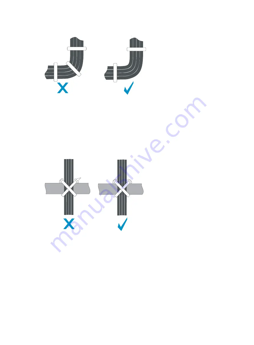
Binding the cables 


When you route cables through sharp sheet metal penetration points or along sharp edges of 
mechanical parts, use bushings or take any other action to protect the cables from being cut or 

abraded. The sheet metal penetration points must be smooth and fully rounded. 


When optical fibers are inserted into a protective tube, wrap tapes around the edges of the 
protective tube to protect optical fibers from being cut. 


After binding the cables, cut the excess from the ties, leaving no sharp or angular tips. See 

Figure 

87

Figure 87


Cutting the cable ties 


Route, bind, and attach excess cables for easy, safe maintenance activities and proper operations.  


Do not tie the power cords to the slide rails.  


When you connect a cable to an articulated part, for example, when you connect a grounding 
cable to a rack door, leave enough slack in cables and make sure they are not stressed from any 

movement of the part. 


Cables must be protected at points where they might rub or come in contact with sharp edges or 
heated areas. Use high temperature cables near heat sources.  


Fasten heavy or rigid power cords at the connectors to relief stress.  

Summary of Contents for SR8800 Series

Page 1: ...H3C SR8800 10G Routers Installation Guide New H3C Technologies Co Ltd http www h3c com hk Document version T2 080412 20170331 C 3 14...

Page 2: ...her trademarks that may be mentioned in this manual are the property of their respective owners Notice The information in this document is subject to change without notice Every effort has been made i...

Page 3: ...ou enter literally as shown Italic Italic text represents arguments that you replace with actual values Square brackets enclose syntax choices keywords or arguments that are optional x y Braces enclos...

Page 4: ...rmation NOTE An alert that contains additional or supplementary information TIP An alert that provides helpful information Network topology icons Represents a generic network device such as a router s...

Page 5: ...fer from what you have on your device Obtaining documentation To access the most up to date H3C product documentation go to the H3C website at http www h3c com hk To obtain information about installat...

Page 6: ...te 19 Weight support 19 Temperature 19 Humidity 19 Cleanness 20 EMI requirements 20 Grounding 20 Power supply 21 Space 21 Rack mounting 21 Installation tools 23 Installing the router 25 Inspecting the...

Page 7: ...ment 54 Displaying the electrical label data for your router 54 Displaying the card information 54 Rebooting your router 55 Displaying the power supply system 56 Configuring temperature alarm threshol...

Page 8: ...rd specifications 87 MPE base card specifications 87 Subcard specifications 88 OAA module specifications 91 Transceiver module and cable specifications 92 Fan tray specifications 94 Power system speci...

Page 9: ...13 Guidelines 113 Examples 113 Engineering labels for network cables 113 Engineering labels for optical fibers 115 Engineering labels for DC power cords 117 Engineering labels for AC power cords 118 E...

Page 10: ...cal 2 8 SR8812 AC DC Horizontal 2 12 NOTE A main processing unit MPU is the supervisor engine of a router and a line processing unit LPU receives and forwards traffic and provides network services The...

Page 11: ...lots slots 0 and 1 3 LPU slots slots 2 and 3 4 Power module slots NOTE Slot 0 is for an MPU while Slot 1 can be used for an MPU or LPU You can install one or two power modules but intermixing of AC an...

Page 12: ...3 Figure 2 SR8802 rear view 1 Rear cover handle 2 Grounding screw 3 Fan tray 3 2...

Page 13: ...slots slots 0 and 1 3 LPU slots slots 2 to 6 4 Power module slots 5 PoE power entry module reserved currently not available NOTE You can install one or two power modules but intermixing of AC and DC...

Page 14: ...5 Figure 4 SR8805 rear view 1 Rear cover handle 2 Grounding screw 3 Fan tray 1 2 3...

Page 15: ...agement bracket 5 Power module slots 6 PoE power entry module reserved currently not available 7 ESD preventive wrist strap port NOTE You can install one or two power modules but intermixing of AC and...

Page 16: ...7 Figure 6 SR8808 rear view 1 Air filter 2 Grounding screw 3 Rear cover handles...

Page 17: ...lots 0 to 5 8 to 13 3 MPU slots slots 6 and 7 4 Power module slots 5 PoE power entry module reserved currently not available NOTE You can install one or two power modules but intermixing of AC and DC...

Page 18: ...l two power modules for redundancy Table 2 lists the power modules available for the SR8800 routers All these power modules are hot swappable For the specifications of AC power modules see Table 3 For...

Page 19: ...put voltage range 100 VAC to 240 VAC 50 Hz or 60 Hz 100 VAC to 240 VAC 50 Hz or 60 Hz Max input voltage range 90 VAC to 264 VAC 50 Hz or 60 Hz 90 VAC to 264 VAC 50 Hz or 60 Hz Max input current 12 A 1...

Page 20: ...voltage error Output Green Steady on The power module or power supply is correctly outputting power Off The power module or power supply is absent or has an output voltage error Fault Red Steady on T...

Page 21: ...S3500 D Max output power 1300 W 2000 W 3500 W 3200 W 40 VDC Figure 11 NEPS1300 D 1 Power input LED 2 Power output LED 3 Power fault LED Figure 12 NEPS2000 D DC power module 1 Power input LED 2 Power o...

Page 22: ...cing an overvoltage overcurrent or over temperature condition Off The power module is operating correctly or absent Cooling system Fan trays The SR8800 routers use fan trays for heat dissipation The f...

Page 23: ...2 ALM LEDs Table 7 Description of fan LEDs LED Color Status Description RUN Green Off The fan tray has failed Steady on The fan tray is operating correctly ALM Red Off The fan tray is in a normal stat...

Page 24: ...igure 15 SR8805 airflow 1 Chassis air intake 2 Chassis air outlet 3 Power module air intake 4 Power module air outlet Airflow design for the SR8808 The chassis and power modules of the SR8808 router u...

Page 25: ...intake 2 Chassis air outlet 3 Power module air intake 4 Power module air outlet If you have installed a rear air deflector for the SR8808 router the fan tray cannot pull ambient air in from the rear b...

Page 26: ...nded power extension cables missing safety grounds and wet floors Locate the emergency power off router in the room before installation Shut the power off at once in case accident occurs Unplug all th...

Page 27: ...avy or is to be moved over a long distance use a mechanical lift For personal safety move the router carefully in cooperation with several people for short distance movement When moving the router hol...

Page 28: ...mperature environment dry the router before powering it on to avoid short circuits To ensure the normal operation of the router make sure the room temperature meets the requirements described in Table...

Page 29: ...erference EMI sources from outside or inside of the switch and application system adversely affect the switch in a conduction pattern of capacitance coupling inductance coupling electromagnetic wave r...

Page 30: ...ake sure the power source of the installation site is steady and can meet the input requirements of the power modules and parameters such as rated voltage For the power consumption and power module sp...

Page 31: ...outer edge of the front rack door is greater than 125 mm 4 92 in and the depth of the rack distance between the front and back doors is greater than 800 mm 31 50 in Figure 19 Rack depth The rack is a...

Page 32: ...kets to the router Fixing the cable management brackets to the router M6 12 screw 1 set Fixing the router to the rack M6 cage nut 1 set ST2 9 9 5 self tapping screw 1 set Fixing the cable management b...

Page 33: ...ssories and installation tools are not included in this section The accessories and installation tools might vary depending on the rack model For more information see the installation guide of the cor...

Page 34: ...e meets all the requirements Using the packing list supplied with your router inspect the router to be sure that you have all the items listed in the packing list and verify that the router was not da...

Page 35: ...rack is a measurement of one rack unit RU 44 45 mm or 1 75 in As shown in callout 2 in Figure 21 each 1 RU has three holes with center to center spacing between the holes of 15 87 mm 0 63 in 15 87 mm...

Page 36: ...the front square holed brackets of the rack To install cage nuts to the rack 1 Align the mounting bracket with the left rack post making sure that the bottom edge and the slide rail are level Mark the...

Page 37: ...e SR8808 has two cable management brackets The signal cable management brackets are installed at the upper part of the router and the power cord management brackets are installed at the lower part of...

Page 38: ...SR8812 For the SR8802 SR8805 SR8812 install the cable management brackets to the mounting brackets cable management brackets and mounting brackets are required at both sides of the chassis Figure 24...

Page 39: ...he SR8802 SR8805 SR8812 Installing the mounting brackets Before installing the router to the rack install the mounting brackets to the chassis Figure 25 shows how to install the mounting brackets to a...

Page 40: ...tall an impedance carrier 1 Loosen the captive screws on the air filter to remove the air filter 2 Install the impedance carrier and fasten the captive screws on the impedance carrier Figure 26 Instal...

Page 41: ...rect holes Verifying the installation After the installation is completed check the installation against the following checklist Make sure all check results are positive Table 13 Installation checklis...

Page 42: ...m the router chassis 2 Use the grounding screws to attach one end of the grounding cable to the chassis 3 Connect the other end of the grounding cable to the grounding strip of the rack in the same wa...

Page 43: ...power module Make sure the power switch is in the OFF position before installing a power module Installing a DC power module 1 Remove the air filter frame of the power module and gently pull the DC p...

Page 44: ...nd supporting the bottom of the power module with the other hand insert the power module slowly along the guide rails to fully seat it in the backplane 3 Fasten the mounting screws on the power module...

Page 45: ...ocks the power module in place Figure 32 Installing a power module Installing a card All the cards excluding subcards for the SR8800 routers are hot swappable You can install MPUs and LPUs in a simila...

Page 46: ...he bottom of the card with both hands slowly push the card into the slot along the guide rails 3 Close the ejector levers to fully seat the card in the backplane 4 Position the screws into the holes a...

Page 47: ...remove the SPE base card if the router is operating 2 Install the subcard in the base card a Rotate out the ejector levers on the subcard simultaneously with both hands b Push the subcard with bottom...

Page 48: ...AC power should be led through an external lightning device into the SR8800 router For more information see Appendix C Lightning protection The power switch is in the OFF position Connecting an AC po...

Page 49: ...le 3 Pull the bail latch to the left to secure the power cord plug 4 Connect the power cord to the power source Figure 36 Connecting an AC power cord Connecting an NEPS3500 A AC power cord CAUTION Typ...

Page 50: ...3 Connect the plug of the AC power cord to the power receptacle of the power module as shown in callout 1 on Figure 39 Then attach the bail latch to the power module as shown in callout 2 on Figure 39...

Page 51: ...cover in time To connect a DC power cord 1 Remove the protection cover from the DC power module 2 Loosen the fastening screw on the wiring terminals with a Phillips screwdriver 3 Connect one end of th...

Page 52: ...he installation against the following list Ensure that all check results are positive Table 14 Installation checklist Item Result Remarks Yes No The grounding cable is correctly grounded Power modules...

Page 53: ...or connecting to the console port of the router and a DB 9 female connector at the other end for connecting to the serial port on the console terminal Figure 42 Console cable Table 15 Console cable pi...

Page 54: ...router When you remove the console cable first unplug the RJ 45 end and then the DB 9 end Setting up a configuration environment 1 Select Start All Programs Accessories Communications HyperTerminal T...

Page 55: ...by the HyperTerminal connection 4 Set Bits per second to 9600 Data bits to 8 Parity to None Stop bits to 1 and Flow control to None and click OK Figure 46 Setting the serial port parameters 5 Select F...

Page 56: ...7 HyperTerminal window 6 On the Settings tab set the emulation to VT100 and click OK H3C recommends that you select the Windows keys option Figure 48 Setting the terminal emulation in Test Properties...

Page 57: ...ter To power on the router 1 Turn on the power switch of the power source providing power to the router 2 Turn on the power switch on the router Before the router is powered on the following informati...

Page 58: ...he prompt H3C The SR8800 router provides a CLI For more information about the CLI see H3C SR8800 Router Series Fundamentals Configuration Guide NOTE The output depends on your router model Verificatio...

Page 59: ...work through category 5 or above twisted pairs that are equipped with RJ 45 connectors No Ethernet twisted pair cables are shipped with the router Prepare them yourself To connect a 10 100 1000BASE T...

Page 60: ...nd radius must be not less than 40 mm 1 58 in the minimum dynamic bend radius is 20 D and the minimum static bend radius is 10 D D indicates the outer diameter of fiber jackets If the fiber has to pas...

Page 61: ...per and absolute alcohol to clean the end face of the fiber connector 3 Connect one end of the fiber to the SFP module of the router 4 Connect the other end of the fiber to the peer device Figure 51 C...

Page 62: ...des of the chassis and bound at cabling racks on chassis sides depending on the available equipment room condition Put all the data signal cable adapters neatly under the chassis instead of any places...

Page 63: ...luding the card name serial number MAC address manufacturing date and vendor name Display the electrical label data for the card in slot 3 on your router Sysname display device manuinfo slot 3 Slot 3...

Page 64: ...ware version of the router NONE No card is in the slot Mismatched The software version does not support the card and thus cannot be uploaded Rebooting your router CAUTION Router reboot can interrupt n...

Page 65: ...led by default Available in user view Enable the scheduled reboot function and specify a reboot waiting time schedule reboot delay hh mm mm Optional The scheduled reboot function is disabled by defaul...

Page 66: ...information of the sensors on the cards including the current temperature and temperature thresholds Display the temperature information of the cards on the router Sysname display environment System...

Page 67: ...ff Takes no action Warning Sends warning messages Reset Resets the failed card Isolate Shuts down the failed port isolates the failed card prohibits the failed card from loaded or powers off the faile...

Page 68: ...bps Ethernet interfaces ATM or POS 155 Mbps 622 Mbps 2 5 Gbps interfaces Yes Yes XFP 10 Gigabit small Form factor Pluggable Generally used for 10 Gbps Ethernet interfaces and 10 RPR interfaces Yes No...

Page 69: ...mode transceiver modules and m for other transceiver modules If the transceiver module supports multiple transfer medium every two values of the transfer distance are separated by a comma The corresp...

Page 70: ...erface type interface number Available for all transceiver modules Display the currently measured values of the detection parameters of the transceiver module in a specified interface display transcei...

Page 71: ...wer is low TX power high TX power is high TX power low TX power is low TX bias high TX bias current is high TX bias low TX bias current is low Temp high Temperature is high Temp low Temperature is low...

Page 72: ...meters Temp C Digital diagnosis parameter temperature in C with the precision to 1 C Voltage V Fault detection parameter voltage in V with the precision to 0 01 V Bias mA Fault detection parameter bia...

Page 73: ...g correctly The main processing unit MPU is operating correctly The console cable has been connected to the console port of the MPU If no problem is found the following reasons might apply The console...

Page 74: ...tput LEDs are off or the fault LEDs are on the power module does not operate correctly To troubleshoot the power supply system 1 Examine the power cord connections If a power cord is loose re plug the...

Page 75: ...of the chassis are not blocked If they are blocked clean them to keep the air flow smooth 3 Verify that the fan tray is fully seated You can unplug the fan tray plug it again and verify that the fan...

Page 76: ...me time the RUN LED on the LPU flashes and the ALM LED on the LPU is off When the RUN LED is off the LPU fails To troubleshoot the LPU 1 Verify that the MPU is operating correctly For more information...

Page 77: ...command to activate the interface and examine the LED status 7 Use the display interface command to verify that the interface is up If the interface is not up use the undo shutdown command to bring i...

Page 78: ...nd make sure the wrist strap makes good skin contact and is well grounded 2 Make sure the power switch of the DC or AC power module is in the OFF position before removing it 3 Remove the cables connec...

Page 79: ...n NEPS1800 A power module 1 Pull the handle of the power module downward to the unlock position Gently move the power module to unseat it from the backplane of the power frame 2 Supporting the bottom...

Page 80: ...wdriver to fasten the captive screws on both sides of the power frame 7 Pull the handle of a power module downward to the unlock position 8 Gently push the power module into the specified slot of the...

Page 81: ...of the air filter frame Figure 56 Removing the air filter of a power module 2 Use clear water to gently wash the air filer do not rub the air filter and air dry it 3 Put the black air filter into the...

Page 82: ...ction cover Replacement procedure 1 Loosen the captive screws on both sides of the card to be removed 2 Rotate out the ejector levers to unseat the card from the backplane of the chassis 3 Slowly pull...

Page 83: ...operating 3 Replace the subcard on the base card a Rotate out the ejector levers to unseat the subcard from the SPE base card b Slowly pull out the subcard along the guide rails as shown in Figure 60...

Page 84: ...r hands away from the spinning fan blades when removing the fan tray To ensure normal operation of the router do not keep the router working without a fan tray for a long time Fan trays are hot swappa...

Page 85: ...e a Phillips screwdriver to fasten the captive screws on both sides of the fan tray panel Figure 61 Removing a fan tray for an SR8802 SR8805 SR8812 Replacing a fan tray for an SR8808 The fan tray of a...

Page 86: ...assis air filter is shipped with the router by default You can order one as needed Replacing chassis air filters for an SR8808 1 Use a Phillips screwdriver to remove the captive screws on the front an...

Page 87: ...ilter slowly pull the air filter out of the chassis as shown in callout 2 on Figure 64 3 Install the cleaned air filter to the router Figure 64 Replacing the air filter for an SR8802 SR8805 SR8812 SR8...

Page 88: ...f you want to continue to use the CF card execute the mount cf command in user view to load the CF card again For more information about the umount and mount commands see H3C SR8800 Router Series Fund...

Page 89: ...vot the clasp down to the horizontal position and then pull SFP the transceiver module out of the socket as shown in Figure 67 3 Put the removed SFP transceiver module in an antistatic bag or its orig...

Page 90: ...81 Figure 67 Removing an SFP transceiver module Figure 68 Installing an SFP transceiver module NOTE Remove the fibers if any from the SFP transceiver module before installing it...

Page 91: ...tion Weight Dimensions H W D Height RU SR8802 1081 W AC 968 W DC Net weight 25 kg 55 11 lb Full configuration 40 kg 88 18 lb 265 442 443 mm 10 43 17 40 17 44 in 6 RU SR8805 1845 W AC 1652 W DC Net wei...

Page 92: ...W to 60 W 2 94 kg 6 48 lb 40 400 380 mm 1 57 15 75 14 96 in SPC XP4LA 82 W to 95 W 3 08 kg 6 79 lb 40 400 380 mm 1 57 15 75 14 96 in SPC GT48LA 72 W to 125 W 3 22 kg 7 10 lb 40 400 380 mm 1 57 15 75...

Page 93: ...1 46 6 50 5 59 in PIC CL2G8L 18 22 W to 33 W 0 65 kg 1 43 lb 37 165 142 mm 1 46 6 50 5 59 in PIC CLS4G4L 30 86 W to 37 W 0 65 kg 1 43 lb 37 165 142 mm 1 46 6 50 5 59 in PIC CHS1G4L 24 W to 30 W 0 60 k...

Page 94: ...ut the SR8800 card LEDs see Appendix B LEDs For more information about the SR8800 cards see the corresponding datasheet of the cards MPU specifications CAUTION USB ports on the MPU provide only connec...

Page 95: ...2SRP1G3 and SR02SRP2G3 are supported by Release 3622 and later SPC card specifications Model Description Available transceiver modules and cables SPC XP2L 2 port 10GBASE R W optical Ethernet interface...

Page 96: ...rface card SFP LC 10GE SFP module 10GE SFP cable NOTE The SPC XP2LA SPC XP4LA SPC GT48LA SPC GP24LA SPC GP48LA and SPC XP16R are supported by Release 3622 and later SPE base card specifications Model...

Page 97: ...GE CWDM SFP fiber module GE SFP copper module PIC GP20R 20 port 1000BASE X optical Ethernet interface card SFP LC FE SFP fiber module GE SFP fiber module GE CWDM SFP fiber module GE SFP copper module...

Page 98: ...12c STM 4c POS optical interface SFP LC 6 port 1000BASE X optical interface card SFP LC 622M SFP fiber module GE SFP fiber module GE CWDM SFP fiber module GE SFP copper module PIC CSP1L 1 port OC 48...

Page 99: ...X optical interface card SFP LC FE SFP fiber module GE SFP fiber module GE CWDM SFP fiber module GE SFP copper module E1 T1 cable PIC ET32G2L 32 port CE1 CT1 electrical interface 2 DB 28 female connec...

Page 100: ...bo interfaces GE SFP fiber module RJ 45 cable IM IPS 1 console port 2 USB ports reserved 2 x 10 100 1000 BASE T copper ports 2 x GE combo interfaces GE SFP fiber module RJ 45 cable IM SSL 1 console po...

Page 101: ...ps The PIC ET32G2L subcard does not support the SFP FE SX MM1310 GE or 100 Mbps SFP GE FE LX10 SM1310 Table 34 lists the available SFP modules for the SR8800 routers Table 34 Available SFP modules Typ...

Page 102: ...FP fiber modules and SFP cables for the SR8800 routers Table 35 Available SFP fiber modules and SFP cables Type Available models SFP fiber module SFP XG SX MM850 A SFP XG LX220 MM1310 SFP XG LX SM1310...

Page 103: ...100 VAC to 120 VAC 1800 W 200 VAC to 240 VAC 2 25 kg 4 96 lb NEPS800 A 800 W AC power module 800 W 3 80 kg 8 3774 lb NEPS2000 A 2000 W AC power module 1200 W 100 VAC to 120 VAC 2000 W 200 VAC to 240...

Page 104: ...50 Hz or 60 Hz 90 VAC to 264 VAC 50 Hz or 60 Hz 16 A 2000 W NEPS800 A 800 W AC power module 100 VAC to 240 VAC 50 Hz or 60 Hz 90 VAC to 264 VAC 50 Hz or 60 Hz 12 A 100 V 800 W NEPS1300 D 1300 W DC pow...

Page 105: ...uela Thailand Peru and Philippines Connector outline Power cable outline Connector outline 3 Connector type Code Length Countries or regions where the type of power cords conforms to local safety regu...

Page 106: ...the type of power cords conforms to local safety regulations and can be used legally Other countries or regions using this type of power cords Countries or regions seldom using this type of power cor...

Page 107: ...and can be used legally Other countries or regions using this type of power cords Countries or regions seldom using this type of power cords C20 0404A0C2 3 m 9 8 ft Mainland China Connector outline P...

Page 108: ...bsent Table 41 DC power module LED description LED Status Description IN input Steady on Power is being correctly input Off The power module is absent or has input voltage error OUT output Steady on T...

Page 109: ...The appearance of SR8800 MPUs varies by MPU model Figure 69 takes SR02SRP1F3 for illustration CF card status LED Table 43 CF card status LED description LED Status Description CFS green Steady on The...

Page 110: ...orrectly ALM red Steady on An alarm occurs Off No alarm occurs MPU status LEDs The description of the MPU status LEDs varies by MPU models Table 46 shows the LED description of an SR02SRP1M3 SR02SRP1E...

Page 111: ...alarm has occurred Off No alarm has occurred SPC card LEDs The description of the SPC card LEDs varies by card models LINK ACT LED Each interface on the following SPC cards has a LINK ACT LED SPC GT4...

Page 112: ...sent Flashing green Data is being transmitted and or received on the combo interface LINK and ACT LEDs Each interface on the following SPC cards has a LINK LED and an ACT LED SPC XP2L SPC XP4L SPC GP4...

Page 113: ...ty or is starting up Off The card is faulty or not in position Flashing one time per second The card is operating correctly Fast flashing eight times per second The LED flashes fast when the card is s...

Page 114: ...an attach the power strip to the rack workbench or wall of equipment room After you connect the AC power cord from the router to a socket on the power strip verify that the green RUN LED on the strip...

Page 115: ...n the current exceeds the threshold and closes the electric circuit when the current drops below the threshold 6 Multifunctional socket It is used to connect the power module of the router Installing...

Page 116: ...nd look at the indicators on the lightning protector to verify that the connection is correct 5 Use nylon ties to bundle the cables neatly Installation precautions The performance of the port lightnin...

Page 117: ...the cable A mark TO is located at the lower right corner of the label to identify the peer end of the cable on which the label is affixed As shown in Figure 71 write a signal cable label as follows W...

Page 118: ...r shaped with fixed dimensions It is applicable to both signal cables and power cables A mark TO is located at the upper left corner in the right area of the label to identify the peer end of the cabl...

Page 119: ...ormation about using a label printer see the user guide of the printer To write labels use black markers A marker has two nibs Be sure to use the smaller nib to write labels Affixing labels After prin...

Page 120: ...he recessed rectangular area on the identification plate You can stick the label to either side of the identification plate Be sure to affix the labels on the same side of the identification plates A...

Page 121: ...or on the right side of the cable in vertical cabling Make sure the label is facing out as shown in Figure 77 Figure 77 Affixed labels Affixing a generic label The requirements for affixing a generic...

Page 122: ...bents or other positions that might affect cable installation when you stick a label or bundle a cable tie with a power cord identification plate Bundle cable ties at the same positions of power cords...

Page 123: ...cify the rack number chassis number and Ethernet port number for example B02 03 12 If you connect the cable to a terminal or an NMS specify the location number of the terminal or the NMS The informati...

Page 124: ...on labels affixed to the fiber between two devices Content Meaning Example MN B C D R T MN Rack number M Row number of the rack in the equipment room in the range of A to Z N Column number of the rac...

Page 125: ...T MN Row number and column number of ODF M Row number of the rack in the equipment room in the range of A to Z N Column number of the rack in the equipment room in the range of 01 to 99 For example G...

Page 126: ...umber in the equipment room Power cabinet side MN identifies the row and column number of the power distribution equipment like the control cabinet and distribution box BC identifies the row and colum...

Page 127: ...on the labels for PGND cables should be given in the similar way Engineering labels for AC power cords These labels are affixed to the AC cables that provide power for cabinets and protection groundin...

Page 128: ...ent room B01 AC power socket side The power cord is connected to the loaded cabinet of Row B Column 01 in the equipment room Engineering labels for devices These labels can be affixed to any device Yo...

Page 129: ...her If you route them in parallel make sure the space between a power cord bundle and a signal cable bundle is at least 30 mm 1 18 in Use the correct ties to bind the cables Do not bind cables with jo...

Page 130: ...he excess from the ties leaving no sharp or angular tips See Figure 87 Figure 87 Cutting the cable ties Route bind and attach excess cables for easy safe maintenance activities and proper operations D...

Page 131: ...122 Cable management examples The devices in the following figures are for illustration only Figure 88 Network cable management...

Page 132: ...89 Optical fiber management Use strapping tapes to carefully bind optical fibers Avoid excessive force For more information see the instructions shipped with the strapping tapes Figure 90 Power cord...

Page 133: ...laying the power supply system 56 E Environment requirements 82 Examining the installation site 19 Examples 1 13 F Fan failure 66 Fan LEDs 99 Fan tray specifications 94 Filling in labels 1 10 G Ground...

Page 134: ...125 S Safety recommendations 17 SPC card LEDs 102 SPE MPE card LED 104 Subcard LEDs 104 T Technical support 68 V Verifying and diagnosing transceiver modules 59 Verifying the installation 43...

Reviews: